Single op-amp
Hi,
A year or so ago I had my CD63KIS modified (new clock and output stage biased to class a). When it came back it sounded better and in the meantime I'd discovered this site so I made a few changes to voltage regs diodes etc. and left it. Bought a CD67 and started from scratch.
I decided to revisit the 63 and see if there were any more improvements that I could make with the benefit of (your) experience.
When I looked at the new output stage I found that the analogue output from the dac was taken to a new board sat on top of the hdam cans bipassing the normal filter and dual op-amps completely.
On the board is a new filter, transistors (one per channel, presumably to bias to class a) and a single op-amp per channel (LM6171).
Has anyone else tried replacing the dual op-amps with a single? From a technical viewpoint what would be the supposed benefit of doing this? What are the likely downsides.
Regards
Pete

Re: Single op-amp
Interesting.
You may be the first on this thread to have heard a 'class A' output.
Who did the mods ??
As Rowe said, can you post pictures of the top and bottom of the board and any values you can see?
Thanks
Andy
Chivvyp said:
On the board is a new filter, transistors (one per channel, presumably to bias to class a) and a single op-amp per channel (LM6171).
Interesting.
You may be the first on this thread to have heard a 'class A' output.
Who did the mods ??
As Rowe said, can you post pictures of the top and bottom of the board and any values you can see?
Thanks
Andy
rowemeister said:Chivvyp can you post some pics.")
Brent
I'll try to get some photos tonight. Probably only the top as the board is soldered to the hdam cans and I don't want to remove it before I have some idea of what I'm going to do with it.
re the tangentsoft links - I just built a PPA headphone amp from them and biased the opamps in that (using a fet cascode rather than a single). To be honest I can't say that I noticed any difference before and after adding the class a bias but the basic amp was stunning and probably exceeded my hearing capability anyway.
Any comments on the general principle of using a single op-amp rather than a dual.
Regards
Pete
The LM6171 may be being used to perform differential to single-ended conversion and LPF duties (it is very well suited to this task) but then why not use half of the existing circuit? So this is unlikely unless they have a standard board they use in various players.
It may be that they took only LO/RO (or LON/RON) from the DAC (i.e., only single-ended), fed it through a passive filter and then used the op-amp as a buffer and/or to provide a bit of gain to make up for the drop in voltage of not using the differential output.
You can make an op-amp class a by attaching a resistor, CRD or cascoded JFET between the output and the supply rail with the worse (or is it better? can never remember!) PSRR.
A pic would be nice.
I've currently got the first half of the op-amp as normal, and fed to the HDAM which I've converted to be the 2nd stage of the LPF (like in the CD6000 but single-ended). So it is the same circuit as the dual op-amp in principle, though I have the Bessel filter slope. Mine's a 67SE.
I tried various combinations in A/B comparisons (leaving the 2nd half of the dual in circuit and connected to identical interconnects) and I always preferred the discrete op-amp (bass much better).
(HDAM - if you cut the feedback track you get O/P and -VE inputs and it's a fully-functional discrete op-amp - see CD6000 schematics.)
rowemeister said:Chivvyp can you post some pics.
Brent
Well, I took some photos but the filesizes were too big to add in so I had to resize them! Hope they're viewable.
Attachments
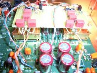
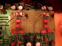
Chivvyp said:The analog inputs are taken from R21 - R24 which are lifted at one end to disable the normal signal route.
Pete
Nice work Pete.
Class A opamp is still an opamp.
tried it various ways but still undecided????
I still had the opamp's signature just different amounts of signature.
personal choice i believe.
Ray's on sounds very good
http://www.diyaudio.com/forums/showthread.php?s=&postid=1069399&highlight=#post1069399
allan
At some time I have to decide whether to a) remove this output stage and go back to better dual op-amps (I have AD8620 in my CD67) and upgrade the filter with silver mica and 0.1%, or b) try to stick some adaptors in the output board and then try some other single op-amps ( I have some AD8610 on sockets in my PPA which I'd like to try).
In the meantime I have some Rubycon ZAs coming to put in by the DAC and the opamps and I'll probably lift the resistors near the output sockets as I think there's still a connection from them backwards through the DC block caps HDAM etc which probably isn't helping matters. Then I'll have a listen and decide whether to kill it via route a or b above
Pete
Speaking of electrolytic capacitors...
A while back I wrote that I had used Panasonic FM series in a DVD player and found the results harsh. The original power supply caps were smallish Cerafine's.
Well, strike that. Yesterday I replaced the op-amps with LM4562's and put .1uf metalized MKP film bypasses on the analog and digital supplies to the DAC, and there was no more harshness. This Pioneer DV47ai is still no match for my less-than-loony modified CD63. It has more bass, but musical lines are much harder to hear. My CD63 has the stock transformer, regulators, clock, and only Pany FA electrolytics, so that could account for the bass.
The DV47ai has the stock Elna Tonerex DC blocking caps but I added .1uf bypasses. I could replace these with Black Gate N types, but I'm not sure the cost/effort is worth it. The stereo BB Dac chip has left and right analog supply pins, but Pioneer uses the same supply - not even separate bypasses. I think this is the source of the musical confusion, but it would be a major effort to address. Oh, well, some boxes have great mod potential and most don't!
FYI Yanks, Digikey has some surface mount LM4562 in stock now, but no dips yet.
markk02474 said:
The stereo BB Dac chip has left and right analog supply pins, but Pioneer uses the same supply - not even separate bypasses. I think this is the source of the musical confusion, but it would be a major effort to address.
Remove the links or resistors to the left right supply (dac) and pop in 2 cheap regs and supply from 10+v from elsewhere and see how much it improves. Also change the caps after the regs.
Brent
I'll explain "major effort". The audio board is on the bottom. Two daughter cards, the drive, 8 cables, and 20 screws have to come out to remove the audio board. Much more work than a CD63 and works poorly for listening after every change.
The chips are all SMD on the underside with 0.5cm clearance to the chassis bottom. The analog power traces to the DAC connect and run under it, so I would have to carefully pry up the two +Vcc legs and solder wires to them from the regulators+bypass caps. There's probably enough clearance to glue 7805/7905's + low ESR Ta SMT or small electrolytic bypasses to the underside. Its just not a project I'm eager for at the moment...
The chips are all SMD on the underside with 0.5cm clearance to the chassis bottom. The analog power traces to the DAC connect and run under it, so I would have to carefully pry up the two +Vcc legs and solder wires to them from the regulators+bypass caps. There's probably enough clearance to glue 7805/7905's + low ESR Ta SMT or small electrolytic bypasses to the underside. Its just not a project I'm eager for at the moment...
Going back to cd attenuation 
I bought some Goldenjack -14db attenuators. They are well made and well soldered. I reverse engineered them to see what resistors they used.....lo and behold the same 0.1% resistors I used LOL.
The values do differ though. Where I used 1K78 and 475 ohm res (-13.5db) they have used 30K and 10K (-14db). Both 'L' type.
Time to test.
Brent
Hi Rowe,
the basic difference between your values and Golden are the source impedance seen by the power amp.
Using the usual ten times factor.
your 1780 & 475 suits Zin >5k
Golden 30k &10k suits Zin>100k
Some difference.
If you plug in some typical values for Zin you begin to see the effect.
Zin=10k and your attenuation falls from -13.5db to -13.8 db, an insignificant 0.3db change.
Golden's version falls from -12db to -16.9db. a very significant 4.9db change.
Similarly the RF filter will change it's time constant much more when the Rs of the attenuator is added to the series R inside the power amp. Golden's will roll off the treble quite badly, whereas your's will make a relatively small change to the treble, but still significant if the grounding cap is bigger than about 750pF.
When looked at from the perspective of the source feeding the attenuator then the load seen by the source is also very different.
Using the same Zin>=10k
Golden loads the source with >35k
your load is >2k2.
How many sources work well with loads over that range?
Hi Andrew,
Is ZIN the input impedance of the amp? I always had problems with working out whether this related to the power amp or the preamp or a combination of both
With my amp modules I believe the impedance is around 22k but my volume pot is 50K.
Does this make the ZIN 50K (or 22 or 72 or something more complicated)?
I chose my attenuation to match 22k on the basis that I'd fit a 20K pot in the future.
Regards
Pete
- Home
- Source & Line
- Digital Source
- Marantz CD63 & CD67 mods list