What you need to do is to buy a 50VA 2X12V toroidal transformer. Now look at the circuit diagram of the CD63. Disconnect the stock transformer's secondary winding from U308(12V), U309(earth) and U310(12V) and replace them by the 50VA Tx. You should also change C813 to a bigger cap. say 10000UF to 22000uF. For C814 change it with a 6800uF or 10000uF cap.
You may wish to see the photo in my thread 19085 for reference: http://www.diyaudio.com/forums/digital-source/54009-marantz-cd63-cd67-mods-list-1909.html
Here you can find the service manual if you don't have it: Ray's Audio Page
With a bigger Tx when the CD drive is run the voltage drop from the Tx output is around 0.5V but with the stock Tx you will find that the voltage can drop by almost 5V. Once a new Tx is fitted you will hear a tighter bass and the LF is much more extended. Worth a try and it is not that difficult
Tnks, that doesn't look too difficult! I had a look at some transformers, but they are pretty big to fit in and not very cheap (about 40 euro), for exemple:
Ringkern transformatoren voor 230V toepassingen
Diameter 80mm
Height 33mm
The only space I have is behind the cd tray, but then I wouldn't be able to put the brace back on top of the old transformer. The tx on the link you send seems much smaller. Are there smaller transformers that can do the job?
The 50VA 12vX2 Tx I used is actually bigger than yours with dia 80mm and 35mm height.
Toroidal 230V Mains Transformer 50VA 0-12V 0-12V | eBay
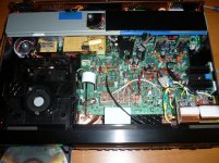
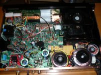
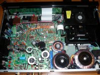
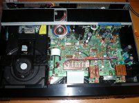
I can fit this 50VA TX and two other smaller TXs (30VA 15Vx2 for the opamps and a 7VA 12Vx2 for the display panel) behind the CD tray. You can see that I can still have enough room to put back the metal bridge on top. See my two completed projects on a CD63SE and on a CD63 MKII KI below.
If you want to use a smaller one a 30VA 12Vx2 TX can also do the job but it is not as good as a 50VA Tx from stability point of view but it should be better than the stock TX.
Attachments
Last edited:
Nice pics! thanks for sharing
I like the idea of the little multiple LT1763 power reg board. I've got some parts ordered to make one for mine. The regulators you're using to feed the LT1763s is adjustable isn't it? What voltage do you find it best to have that set to?
I can see you've used an LM317 500ma 'Sure Electronics' regulator one 1 of the installs. I've got one of those here and was thinking of using that. Do you think it's adequate for the job?
Also, I can see that sometimes you've put an extra large cap on 1 of the LT1763s. Do you reckon that's needed?
thanks,
James
The LT1763 I used is 5V fixed output and not adjustable. The output voltage MUST be set to 5V to supply the DAC, decoder and servo ICs etc. The Sure regulator is to step down the voltage from the digital rail to 9V for the LT1763s and to provide low noise source supply. The lower the supply voltage to the LT1763 the more o/p current you can get (see the data sheet yourself). From my experience 500mA for the 5 pcs of LT1763 is sufficient. Large caps fitted to the o/p of LT1763s are not needed but there is no harm to add them either.Nice pics! thanks for sharing
I like the idea of the little multiple LT1763 power reg board. I've got some parts ordered to make one for mine. The regulators you're using to feed the LT1763s is adjustable isn't it? What voltage do you find it best to have that set to?
I can see you've used an LM317 500ma 'Sure Electronics' regulator one 1 of the installs. I've got one of those here and was thinking of using that. Do you think it's adequate for the job?
Also, I can see that sometimes you've put an extra large cap on 1 of the LT1763s. Do you reckon that's needed?
thanks,
James
thanks.The LT1763 I used is 5V fixed output and not adjustable. The output voltage MUST be set to 5V to supply the DAC, decoder and servo ICs etc. The Sure regulator is to step down the voltage from the digital rail to 9V for the LT1763s and to provide low noise source supply. The lower the supply voltage to the LT1763 the more o/p current you can get (see the data sheet yourself). From my experience 500mA for the 5 pcs of LT1763 is sufficient. Large caps fitted to the o/p of LT1763s are not needed but there is no harm to add them either.
Yes, I know this LT1763 which is used is the fixed 5v output version. I was talking about the voltage chosen for the output of the step-down regulator. Because it seems from the datasheet the 5v LT1763 has very low dropout of only 0.5v minimum. So, if the digital rail is being fed from a nice 50va tx, there is a fairly large range of voltage you can choose for the output of this step-down regulator. I wondered if maybe if this voltage is closer to the LT1763 desired output, like say 6v for example, if there are some other benefits like better ripple rejection due to less 'work' for this little regulator. Or maybe it makes no difference
thanks again,
James
thanks.
Yes, I know this LT1763 which is used is the fixed 5v output version. I was talking about the voltage chosen for the output of the step-down regulator. Because it seems from the datasheet the 5v LT1763 has very low dropout of only 0.5v minimum. So, if the digital rail is being fed from a nice 50va tx, there is a fairly large range of voltage you can choose for the output of this step-down regulator. I wondered if maybe if this voltage is closer to the LT1763 desired output, like say 6v for example, if there are some other benefits like better ripple rejection due to less 'work' for this little regulator. Or maybe it makes no difference
thanks again,
James
I used 9V for the input of the LT1763-5. 6V may be too close to its working voltage. Feeding a lower input voltage you will have better current output from the LT1763. With a 50VA 12Vx2 TX you will get about 17-18V DC output after the caps. If you set the output voltage of your step down regulator to 6V then there will be a big voltage drop (more than 10V) which may affect the performance of this step down regulator with generation of heat as well.
Last edited:
Did the servo, dac and driver cap today.
I added 100n pps to the 4x opamps cap (i didn't ordered enough of them last time).
Also, I've added common-mode filter, two class x cap before and after the common mode filter and a varistor on the main pins.
I've also deactivated the DO and its 5V supply.
Quiet impressed SQ is once again a bit better. Can't find the word to describe it, but I can hear it
Now planned are decoder and µcontroller sections. Last thing will be the Flea (and its psu) to reclock the DAC.
Did the servo, dac and driver cap today.
I added 100n pps to the 4x opamps cap (i didn't ordered enough of them last time).
Also, I've added common-mode filter, two class x cap before and after the common mode filter and a varistor on the main pins.
I've also deactivated the DO and its 5V supply.
Quiet impressed SQ is once again a bit better. Can't find the word to describe it, but I can hear it
Now planned are decoder and µcontroller sections. Last thing will be the Flea (and its psu) to reclock the DAC.
Well done. You are progressing well


Do keep us posted.
Did the dac and driver caps today.
I added 100n pps to the 4x opamps cap (i didn't ordered enough of them last time).
Then, I've added common-mode filter, two class x cap before and after the common mode filter and a varistor on the main pins.
I've also deactivated the DO and its 5V supply.
Quiet impressed SQ is once again a bit better. Can't find the word to describe it, but I can hear it
Now planned are decoder and µcontroller sections. Last thing will be the Flea (and its psu) to reclock the DAC.
DOS-CFP and PFM Flea Help needed
Hi Higlander and other.
I purchased Ray's DOS-CFP board and PFM Flea kit and have a couple of questions.
1) The Flea requires an 18V minimum Voltage to operate. I am in the USA with 120V, 60Hz line voltage. Any recommendations of a good stable voltage supply that I could buy/build that would give me the required voltage/current for the board?
2) Has anyone built the DOS-CFP? I am looking for fairly high end components to build the output stage out of. Does anyone have a recommended parts list. Looking for types of capacitors/resistors used that produced great SQ.
3) Looking to also inprove the power supply in the CD as recommended. Anyone using 120V/60 Hz make this mod in your 67SE that could provide assistance in component choices . . . ie. Transformer?
Thanks
BIG TX and BIG smoothing caps are highly recommended, in particular, for the servo supply. This will ensure there is no fluctuation of voltage when the CD drive is run as it draws current on starting up and during operation. I have used a scope to measure the transient voltage dip and it can go down by 4-5V in milli of a second when the stock TX is used. With a BIG TX and caps the transient dip will be less than 0.5V and with very steady supply voltage all the time to the servo circuits. What you will get at the end of the day with a BIG TX and BIG smoothing caps is very tight and extended bass.
To my knowledge the servo circuit design of CD67 is better than CD63 as it is regulated but I still think BIG Tx and caps will certainly help. You are right there is only one clock of 16.xxx MHz for both DAC and servo circuit which is different form CD63 which uses two separate clcoks (16.xxx and 8.xxx MHz).
Hi Higlander and other.
I purchased Ray's DOS-CFP board and PFM Flea kit and have a couple of questions.
1) The Flea requires an 18V minimum Voltage to operate. I am in the USA with 120V, 60Hz line voltage. Any recommendations of a good stable voltage supply that I could buy/build that would give me the required voltage/current for the board?
2) Has anyone built the DOS-CFP? I am looking for fairly high end components to build the output stage out of. Does anyone have a recommended parts list. Looking for types of capacitors/resistors used that produced great SQ.
3) Looking to also inprove the power supply in the CD as recommended. Anyone using 120V/60 Hz make this mod in your 67SE that could provide assistance in component choices . . . ie. Transformer?
Thanks
In the end, I just got another (cheap, 40euro) CD57 mkii. It's now much easier to understand how much it sounds better once modded And, I'll be able to let my friends hear the difference, until they want one too
Sorry for the previous post, i thought i edited it, not quoted it XD
And, I'll be able to let my friends hear the difference, until they want one too Sorry for the previous post, i thought i edited it, not quoted it XD
Beware. Once your friends have listen to your modded CDP you will be asked to do one for each of them. Like me I have modded five CD63s for my friends and orders are still flooding inIn the end, I just got another (cheap, 40euro) CD57 mkii. It's now much easier to understand how much it sounds better once modded
Sorry for the previous post, i thought i edited it, not quoted it XD
Have you checked your remote if the battery is running low ?Hello,
if somebody can give me a tip!
After I unite instructions to Ray's
Mods has made is a problem with the
IR Receiver appeared.
I can serve the player only from 10 cm of distance over the remote control.
Does somebody have an idea where the mistake is?
Hi Higlander and other.
I purchased Ray's DOS-CFP board and PFM Flea kit and have a couple of questions.
1) The Flea requires an 18V minimum Voltage to operate. I am in the USA with 120V, 60Hz line voltage. Any recommendations of a good stable voltage supply that I could buy/build that would give me the required voltage/current for the board?
2) Has anyone built the DOS-CFP? I am looking for fairly high end components to build the output stage out of. Does anyone have a recommended parts list. Looking for types of capacitors/resistors used that produced great SQ.
3) Looking to also inprove the power supply in the CD as recommended. Anyone using 120V/60 Hz make this mod in your 67SE that could provide assistance in component choices . . . ie. Transformer?
Thanks
Ray's flea requires 18V supply and what you should have done was when you ordered the flea from Ray you should request him to order a 18V voltage regulator for you from his known source. In my case Ray ordered the 18V voltage regulator for me when I purchased the 2 fleas from him. Ray provides very good service indeed
I cannot help you on the DOS question as I have not used one before. I mainly used discrete opamps in my CD63s.
I don't think you have changed the filtering caps for the sero, the DAC and decoder. Just compare your PCB and mine and you will find I have changed a lot of the stock caps in brown color by OSCON SEPC 470uF. It will improve the SQ.
Higlander,
I have checked your pcb to establish where you have placed the Oscons, and have come up with this list:
DAC: CD04, CD07
Decoder: C510, C511
Servo: C120, C122
RF: C504
C124, C134
C106 (on tray pcb)
I also looked on Brent's page and his list comprises: CD04, CD07, C510, C511, C120, C122, C504
+ 1 to go on output of reg (HF) – R107?
I make that 11 in total (If I include both lists). Am I correct in this respect?
Also, are these the correct ones:
Buy Aluminium Capacitors OSCON 105 SMD 470uF 6.3V, 6SVP470M Sanyo 6SVP470M online from RS for next day delivery.
Sorry for the oodles of questions. Your help is appreciated... many thanks.
hello everyone! this is my first post to this forum.
my name is nick.
after reading... a small part of this thread, i decidet to present my "just a little" moded cd 67se. it has some caps changed with tantalum, some better regs and single op-amps. the next step is to change the supply caps (they are on the way), and... i hope a superclock. the problem is with the money, and... a superclock costs some. the question is: is there a way to find a schematics to build it myshelf?! i asked google, and did not find anyhting. or, i searched the wrong way. if somebody has a schematics to share... i'll be glat to receive it.
the hdam is still operational, but i think i'll do some tests without it.
next days i'll try to share some pics from the moded 67 inside.
so.... any advice is welcome.
Ray's flea requires 18V supply and what you should have done was when you ordered the flea from Ray you should request him to order a 18V voltage regulator for you from his known source. In my case Ray ordered the 18V voltage regulator for me when I purchased the 2 fleas from him. Ray provides very good service indeed
I cannot help you on the DOS question as I have not used one before. I mainly used discrete opamps in my CD63s.
Thanks,
Here in the USA we use 120V, 60Hz so do not think it would work for me.
What AC voltage is used in the UK?
24Vdc Supply Design needed
Anyone out there have a design for a stable 24Vdc supply that I can use inside my player. Input would be 120Vac/60Hz.
Thanks,
Jerry
Thanks,
Here in the USA we use 120V, 60Hz so do not think it would work for me.
What AC voltage is used in the UK?
Anyone out there have a design for a stable 24Vdc supply that I can use inside my player. Input would be 120Vac/60Hz.
Thanks,
Jerry
Higlander,
I have checked your pcb to establish where you have placed the Oscons, and have come up with this list:
DAC: CD04, CD07
Decoder: C510, C511
Servo: C120, C122
RF: C504
C124, C134
C106 (on tray pcb)
I also looked on Brent's page and his list comprises: CD04, CD07, C510, C511, C120, C122, C504
+ 1 to go on output of reg (HF) – R107?
I make that 11 in total (If I include both lists). Am I correct in this respect?
Also, are these the correct ones:
Buy Aluminium Capacitors OSCON 105 SMD 470uF 6.3V, 6SVP470M Sanyo 6SVP470M online from RS for next day delivery.
Sorry for the oodles of questions. Your help is appreciated... many thanks.
They are all correct and you got 100% mark
- Home
- Source & Line
- Digital Source
- Marantz CD63 & CD67 mods list