ash_dac said:
Allan,
I found this website very useful!
http://tangentsoft.net/elec/opamp-linreg.html
I think AD825 is used most often as the op amp.
It's probably used for a number of reasons, and one being the fact that if you are also building op amp modules you can bulk buy AD825!
actually the best place for an opamp is probably psu or dc servo

That comment should upset someone

seen tangent's site, some very helpful info.
I've thinking about doing this
allan
Attachments
poynton said:Hi ,
Ray - where is the quote from??
Andy
Hi Andy,
The quote is from this thread, post 14. It's the thread that Allan posted. Very interesting read. It also has some interesting links to other threads.
Regards,
Ray.
rowemeister said:also not sure what value to use on R1 yet.
Ray if you have some good advice its welcome.
I specialise in lots of areas of electronics but im not major in dc ripple and its filtering.
What I have come up with is my own idea but am unsure of exact values without spending ages with scope.
cheers
Hi Brent,
Well, I read all this wisdom in the datasheet, nothing fancy...
The proposed value for R1 is 120R. The 1.25V reference voltage is across this resistor, so there will be a little over 10mA idle current drawn, which is the minimum load current for the regulator to maintain regulation. So that takes care of that. It won't hurt to use 100R.
If you calculate the bypass cap according to C = 1/(2*pi*f*R) you will get 13uF at a ripple frequency of 100Hz and 120R. So your cap is a bit on the low side.
Regards,
Ray.
awpagan said:I've thinking about doing this
allan
Hey, that looks a lot like this:
(Guido Tent's XO supply)
I use it to supply a Kwak-clock. How ironic

Ray.
Attachments
ash_dac said:
Allan,
I found this website very useful!
http://tangentsoft.net/elec/opamp-linreg.html
I think AD825 is used most often as the op amp.
It's probably used for a number of reasons, and one being the fact that if you are also building op amp modules you can bulk buy AD825!
Isn't that the site I gave in post 1180 ?
6h5c said:
Hey, that looks a lot like this:
(Guido Tent's XO supply)
I use it to supply a Kwak-clock. How ironic
Ray.
yes ray
with separate analogue digital earths
yes andy
It's come back to haunt you
allan
awpagan said:
with separate analogue digital earths
This is interesting - I wonder how much difference it makes?
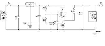
With this circuit, the regulation is performed by the 78XX, the transistor is , I think, called a capacitor multiplier.
Andy
poynton said:
This is interesting - I wonder how much difference it makes?
With this circuit, the regulation is performed by the 78XX, the transistor is , I think, called a capacitor multiplier.
Andy
i've seen ripple been very low on a lm317 with good earthing just in the the overall circuit
ALW in his tests with the lm317 recommends separate earth for the base.
If use the same earths as digital it doesn't give a decent earth,
too much noise.
so the regulation ref point fluctuates.
I was going to use tent's psu just for starters, until i made a super reg.
comments in his posts and test made me think about the 7808,
and how much it may improve?
could be a simple upgrade on a standard cdp.
should transfer to the 317
any thoughts
allan
Clocks and clock psu
Hi.
I've just finished reading through all the various links posted over the last 24hrs !!!
What a difference there is between the LCclock3 and the LCclock2!!!!
Each stage fed from its own 'regulator' with a common reference voltage.
This idea is useable for anyone wanting to feed tha analog, digital, RF, etc stages from their own supply.
The Pat's Lab. clock is similar to Jocko's.
But which gives lowesy rail noise? - I'm confused!!
Andy
Re: Clocks and clock psu
I use the lclock3 in the cd850, just over 1 year now.
Knew it was a 4 layer pcb. just recently saw the schematic
Seeing the schematic, i see why it's 4 layers
Pat's Lab and Jocco's????
Pcb layout may have a lot to do with it?
Digital current pulses affecting analogue or other earth's
CD63/67?
use the earth plane for digital separate from analogue, star grd common.
allan
also
poynton said:Hi.
I've just finished reading through all the various links posted over the last 24hrs !!!
What a difference there is between the LCclock3 and the LCclock2!!!!
Each stage fed from its own 'regulator' with a common reference voltage.
This idea is useable for anyone wanting to feed tha analog, digital, RF, etc stages from their own supply.
The Pat's Lab. clock is similar to Jocko's.
But which gives lowesy rail noise? - I'm confused!!
Andy
I use the lclock3 in the cd850, just over 1 year now.
Knew it was a 4 layer pcb. just recently saw the schematic
Seeing the schematic, i see why it's 4 layers
Pat's Lab and Jocco's????
Pcb layout may have a lot to do with it?
Digital current pulses affecting analogue or other earth's
CD63/67?
use the earth plane for digital separate from analogue, star grd common.
allan
also
Re: Re: Clocks and clock psu
you mean there allready is a star ground on the CD-63/67?
I don't get it?!?
Regards,
Jacco
btw. I'm waiting for my XO2 by tentlabs for my CD-63 any tips for that clock? I have done a mix of ray's and bobwire's mods on my cd-63 (but only with caution: I have NOT replaced any bipolars/ceramics with polar elco's)
awpagan said:
use the earth plane for digital separate from analogue, star grd common.
allan
also
you mean there allready is a star ground on the CD-63/67?
I don't get it?!?
Regards,
Jacco
btw. I'm waiting for my XO2 by tentlabs for my CD-63 any tips for that clock? I have done a mix of ray's and bobwire's mods on my cd-63 (but only with caution: I have NOT replaced any bipolars/ceramics with polar elco's)
Re: Re: Re: Clocks and clock psu
star ground???????
standard form
it uses the top plane as a large earth plate
all analogue and digital have links to it.
uses neutral as earth, via transformer
only way to only way to earth is through the transformer, or any other connected equipment via rca ground
May solve external ground loops?
but at what cost?
probably why i use iec plug
allan
Dr.Gone said:
you mean there allready is a star ground on the CD-63/67?
I don't get it?!?
Regards,
Jacco
btw. I'm waiting for my XO2 by tentlabs for my CD-63 any tips for that clock? I have done a mix of ray's and bobwire's mods on my cd-63 (but only with caution: I have NOT replaced any bipolars/ceramics with polar elco's)
star ground???????
standard form
it uses the top plane as a large earth plate
all analogue and digital have links to it.
uses neutral as earth, via transformer
only way to only way to earth is through the transformer, or any other connected equipment via rca ground
May solve external ground loops?
but at what cost?
probably why i use iec plug
allan
6h5c said:
Hi Brent,
Well, I read all this wisdom in the datasheet, nothing fancy...
The proposed value for R1 is 120R. The 1.25V reference voltage is across this resistor, so there will be a little over 10mA idle current drawn, which is the minimum load current for the regulator to maintain regulation. So that takes care of that. It won't hurt to use 100R.
If you calculate the bypass cap according to C = 1/(2*pi*f*R) you will get 13uF at a ripple frequency of 100Hz and 120R. So your cap is a bit on the low side.
Regards,
Ray.
Cheers Ray. Ill mess about with the values a little.
Re: Clocks and clock psu
Hi Jacco,
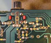
There is a star-ground at the RCA socket. This is a point where all the ground traces from the board meet. The top ground-plane is grounded at this same star-point, but it is also connected through several links to local (analog and digital) groundpoints at the DAC, decoder and analog +/-12V supply caps (U221, U235, U169, U208, U267, U136). So it seems things are not strictly separated. By removing the links (except the one at the star-point) the ground-plane becomes separated.
You should leave U136 in place if you want to keep using the headphone circuit by the way. It has no trace to ground on the bottom layer, so it is the only ground path for it.
Regards,
Ray.
Dr.Gone said:you mean there allready is a star ground on the CD-63/67?
I don't get it?!?
Regards,
Jacco
Hi Jacco,
There is a star-ground at the RCA socket. This is a point where all the ground traces from the board meet. The top ground-plane is grounded at this same star-point, but it is also connected through several links to local (analog and digital) groundpoints at the DAC, decoder and analog +/-12V supply caps (U221, U235, U169, U208, U267, U136). So it seems things are not strictly separated. By removing the links (except the one at the star-point) the ground-plane becomes separated.
You should leave U136 in place if you want to keep using the headphone circuit by the way. It has no trace to ground on the bottom layer, so it is the only ground path for it.
Regards,
Ray.
Attachments
Re: Clocks and clock psu
Hi Allan,
What do you mean by "uses neutral as earth, via transformer"?
Is the neutral of the primairy side connected to the board ground in your player??
Regards,
Ray.
awpagan said:uses neutral as earth, via transformer
only way to only way to earth is through the transformer, or any other connected equipment via rca ground
allan
Hi Allan,
What do you mean by "uses neutral as earth, via transformer"?
Is the neutral of the primairy side connected to the board ground in your player??
Regards,
Ray.
Re: Re: Clocks and clock psu
Ray
i have question
we need active and neutral or positive and earth
for any circiut to operate
standard config, where's earth
allan
6h5c said:
Hi Allan,
What do you mean by "uses neutral as earth, via transformer"?
Is the neutral of the primairy side connected to the board ground in your player??
Regards,
Ray.
Ray
i have question
we need active and neutral or positive and earth
for any circiut to operate
standard config, where's earth
allan
Hi Allan,
In my house, the neutral of the 230V outlet is connected to earth near the main fuse in the fusebox. But the player is floating with respect to earth normally, since the secondairy circuit is by no means connected to the primairy, or grounded.
So neutral = earth over here, but the flat 230V euro-plugs are unidirectional, so there's no telling which wire will be connected to what once you plug it in.
What plugs do you use over there, is it like the british plugs? That way you would always be sure which wire is hot and which is neutral, if the socket is wired correctly that is....
That's why I wondered: is the neutral of the primairy side somehow connected to the board ground in your player?
Regards,
Ray.
Re: Re: Re: Clocks and clock psu
Most modern electrical equipment does not require an earth since it is 'double-insulated'.
The requirement for mains powered equipment is therefore only LINE and RETURN (Neutral). ( although with figure 8 connectors ????)
Theoretically, earthing audio equipment is not required. Indeed, earth loops may / will be formed as we are linking several pieces together.
The 'usual' solution is to connect the amplifier chassis to mains ground, hence the provision of an earthing lug close to the inputs.
All other equipment should be connected to this point, forming a sort of star.
Incidentally, if the piece of equipment does not have a connection to earth, there is little point in having an input noise filter ( see my earlier post ).
Andy
awpagan said:
Ray
i have question
we need active and neutral or positive and earth
for any circiut to operate
standard config, where's earth
allan
Most modern electrical equipment does not require an earth since it is 'double-insulated'.
The requirement for mains powered equipment is therefore only LINE and RETURN (Neutral). ( although with figure 8 connectors ????)
Theoretically, earthing audio equipment is not required. Indeed, earth loops may / will be formed as we are linking several pieces together.
The 'usual' solution is to connect the amplifier chassis to mains ground, hence the provision of an earthing lug close to the inputs.
All other equipment should be connected to this point, forming a sort of star.
Incidentally, if the piece of equipment does not have a connection to earth, there is little point in having an input noise filter ( see my earlier post ).
Andy
Ray
That's what i mean
active & neutral (earth)
AC in transformer, which side is more negative?
andy's right
floating earth in circuit or on pcb
and we are trying to remove mV of noise?
Standard in aust is neutral is either connected to earth at fusebox or
at substation
allan
That's what i mean
active & neutral (earth)
AC in transformer, which side is more negative?
andy's right
floating earth in circuit or on pcb
and we are trying to remove mV of noise?
Standard in aust is neutral is either connected to earth at fusebox or
at substation
allan
awpagan said:Ray
That's what i mean
active & neutral (earth)
AC in transformer, which side is more negative?
andy's right
floating earth in circuit or on pcb
and we are trying to remove mV of noise?
Standard in aust is neutral is either connected to earth at fusebox or
at substation
allan
In the UK, Neutral ( return ) is grounded at the substation.
The EARTH wire should be connected at the fuse box to all cold water pipes via earth bonding straps and then to earth by the water system. This was great in the days of lead water piping but with the advent of plastic feed from the main supply and plastic push-fit pipes internally, maybe an Earth stake rammed into the ground is a good idea. After all, that's what happened in the good old days of crystal sets !!
Andy
- Home
- Source & Line
- Digital Source
- Marantz CD63 & CD67 mods list