Thomo said:Immediately switch off and sniff for smoke.
Duck & cover.
If you need specific help with these two stages, Simon is an expert and is usually only too willing to help.
O RLY

Attachments
Thanks Simon. I'm glad I have a 63-KI in my collection now, so I can compare it to the 67-OSE. I'm looking forward to try the servo-clock, among other things. Plus, it looks very nice too
I have a mods list on-line with all the things I've done to it so far, it's a pretty standard list. I don't think i'm going to put a DOS in there for now; i'm working on a CD72 also, which is going to get an integrated ezDAC, directly connected to the I2S lines, and I'm going to finish that first. But who can tell, maybe after that... I have some PCB left.
Ray
SimontY said:It looks like you've tinkered with decoupling for the driver chips, something I've not touched yet. Got some BGs waiting to be dropped in tho
That should give positive results, especially since the driver voltage is unregulated. I'm thinking about putting low-drop 9V regs in there. Off to dinner now...
Ray
Re: CD63mkII-KI
Hope I will be able to say the same very soon

My first question is:
There seems to be some errors in the CD53 schematics.
On the DAC chip, PIN 23 is RON (Right Negative PWM output)
In the schematic, it connects to RD24 ... RD28 ... Opamp PIN 3.
On this PIN 3 there is a + sign.
On the DAC, PIN 25 is RO (Right Positive PWM ouput)
Again we have DAC PIN25 ... RD22 ... RD26 ... Opamp PIN 2.
On this PIN 2 there is a - sign.
I am confused and need some imput because I am already working on the CDP.
Ricardo
6h5c said:Tadaaa..... finally finished: my CD63-KI!
Hope I will be able to say the same very soon
My first question is:
There seems to be some errors in the CD53 schematics.
On the DAC chip, PIN 23 is RON (Right Negative PWM output)
In the schematic, it connects to RD24 ... RD28 ... Opamp PIN 3.
On this PIN 3 there is a + sign.
On the DAC, PIN 25 is RO (Right Positive PWM ouput)
Again we have DAC PIN25 ... RD22 ... RD26 ... Opamp PIN 2.
On this PIN 2 there is a - sign.
I am confused and need some imput because I am already working on the CDP.
Ricardo
Hi Ricardo,
This is not an error. Marantz reversed the DAC's outputs so the signal is inverted. The second opamp also inverts the signal (the negative input is connected to the first opamp through R606/608), so the total phase shift is 360* and absolute phase is correct in the end.
Ray
This is not an error. Marantz reversed the DAC's outputs so the signal is inverted. The second opamp also inverts the signal (the negative input is connected to the first opamp through R606/608), so the total phase shift is 360* and absolute phase is correct in the end.
Ray
6h5c said:
That should give positive results, especially since the driver voltage is unregulated. I'm thinking about putting low-drop 9V regs in there. Off to dinner now...
Ray
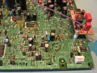
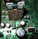
This mod gives huge improvements. I regulated them to +/-7V with LM317/LM377. They are only called upon to supply +/-5V. and the regs only need small heatsinks. It makes a big difference.
If you do a bit of re-routing underneath (it's obvious where) you can make a convenient place to piggy-back a board on, by removing a jumper and an using an unused trace.
There's a ground jumper by the fuse holder that can be removed and replaced by a wire under the board (from tx to star gnd) and you you can re-use the now unused ground-end hole to take you to digital star ground (this hole is hidden by the board).
Attachments

Happy DOS
Done...!!! 


With your help Gentlemen, I succesfully implemented the DOS.
Of course my precious Wife helped a lot also.... She verifies the solder for me.
Even 1 minute after the last solder.... The sound is so much better.... Awesome.
Thank you ALL for the precious help and information.
Tomorrow I will report the improvements...
Ricardo
Done...!!!
With your help Gentlemen, I succesfully implemented the DOS.
Of course my precious Wife helped a lot also.... She verifies the solder for me.
Even 1 minute after the last solder.... The sound is so much better.... Awesome.
Thank you ALL for the precious help and information.
Tomorrow I will report the improvements...
Ricardo
Glenn2 said:
This mod gives huge improvements. I regulated them to +/-7V with LM317/LM377. They are only called upon to supply +/-5V. and the regs only need small heatsinks. It makes a big difference.
If you do a bit of re-routing underneath (it's obvious where) you can make a convenient place to piggy-back a board on, by removing a jumper and an using an unused trace.
There's a ground jumper by the fuse holder that can be removed and replaced by a wire under the board (from tx to star gnd) and you you can re-use the now unused ground-end hole to take you to digital star ground (this hole is hidden by the board).
Hi Glenn
You made me think I need to work the drivers PSU also.
Outstanding work !!!
Ricardo
Glenn2 said:This mod gives huge improvements. I regulated them to +/-7V with LM317/LM377. They are only called upon to supply +/-5V. and the regs only need small heatsinks. It makes a big difference.
If you do a bit of re-routing underneath (it's obvious where) you can make a convenient place to piggy-back a board on, by removing a jumper and an using an unused trace.
There's a ground jumper by the fuse holder that can be removed and replaced by a wire under the board (from tx to star gnd) and you you can re-use the now unused ground-end hole to take you to digital star ground (this hole is hidden by the board).
Thanks, i'm absolutely going to look into that. I have some LM-boards left (the Eddy Wang version) that are perfect candidates.
Glenn2 said:Ray the pdf on your CD-72mkII page is for the CD-63...
Oops... it's fixed! Thanks for pointing that out.
Ray
Re: Happy DOS
Congratulations! Please do report
No smoke? That's excellent, I hope you enjoy it very much.
Ray
RCruz said:Tomorrow I will report the improvements...
Ricardo
Congratulations! Please do report
No smoke? That's excellent, I hope you enjoy it very much.
Ray
- Home
- Source & Line
- Digital Source
- Marantz CD63 & CD67 mods list