imperfectcircle said:I have been following this thread for a while now and have done mods to my cd53 and im currently working on a cd67. My cd67 is only lightly modded right now, bypass hdam, opa2132, upgraded 470uf/16v Rubycon ZL caps for the dac, clock and opamps, and inductor+ferrite for the voltage feed for the dac and clock circuits. I plan on doing more extensive mods in the near future. But I am interested in possibly adding a digital input for this cd67, id like to use my PC as the transport instead of the cd67s cd mechanism. Would this be possible at all???
Hi,
I've been thinking of the same thing. I haven't got anywhere with it yet though. The problem that I see is with getting the raw feed out of the PC. It seems that pretty much all the soundcards I've looked it that provide an SPDIF output already go through some sort of internal data conversion.
Maybe a new topic is called for.
Regards
Pete
Chivvyp said:
Hi,
I've been thinking of the same thing. I haven't got anywhere with it yet though. The problem that I see is with getting the raw feed out of the PC. It seems that pretty much all the soundcards I've looked it that provide an SPDIF output already go through some sort of internal data conversion.
Maybe a new topic is called for.
Regards
Pete
As you rightly observe, most PCs output SPDIF.
So what would be needed is a SPDIF - I2C converter board .
Not a difficult proposition - Front half of an external DAC.
You could also build one with a USB connector.
I think that would be beyond the scope of this thread but would be of interest to many people.
Andy
SimontY said:
Thanks, I'll see if I can buy it cheaply next time I'm near my favourite music shop, or Ebay.
Did I really say I had my own private jazz club? lol. I guess I did
.
.
Simon
http://www.diyaudio.com/forums/showthread.php?postid=815906#post815906
Also take a listen to Companion album - it's live - very much alive.
rowemeister said:Off topic
Any one on here want to by a £200 RCA for £80 to upgrade their listening pleasures.
This cable really brings out what you have done to your cd player.
Cable talk 'The Reference' 1M fitted with Bullets
Crystal copper , cotton filled
Its the best cable they have ever made , apparently they made this cable for Exposure.
Come on Get it fitted to your cdp (you know you want to).
Selling due to an upgrade to Russ Andrews Kimber Crystal Ag.
Brent
ooo sounds like a nice cable, but bell wire ftw
")
Chivvyp said:
Hi,
I've been thinking of the same thing. I haven't got anywhere with it yet though. The problem that I see is with getting the raw feed out of the PC. It seems that pretty much all the soundcards I've looked it that provide an SPDIF output already go through some sort of internal data conversion.
Maybe a new topic is called for.
Regards
Pete
Would something like the usb->I2S or the Spdif->I2S boards used for the DDDAC 1543mk2 kit work???
DDDAC 1543 usb/i2s converter
imperfectcircle said:
Would something like the usb->I2S or the Spdif->I2S boards used for the DDDAC 1543mk2 kit work???
DDDAC 1543 usb/i2s converter
Probably !
Hi all,
Ray, thanks for the coax mod details.Done it with great results on imaging and focus.Any other coax to be added?
I remain a bit mixed with the regulators.Already I've one lm 317 feeding pins 2 and 27 of the dac.Should I replace the on board regs with lm317/lm337 or should I use the lms as pre regs and leave the originals as is.The other option is to use the lms in specific places to feed what?Mine is a cd57
Thanks in advance for the help.
Regards Mike
Hi everyone,
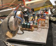
I finished my next mod (as recently described), which was to feed each of my 5v regulators with it's own power supply.
One toroid winding feeds DAC/decoder digital, the same toroid's other winding feeds the DAC clock reference pin.
An additional, fairly large (probably 70va+) toroid is dedicated to DAC/decoder analogue. This transformer is centre-tapped so I only used two diodes to rectify the power (this halves the total available voltage but provides more current, I think). This one is smoothed by 3 x 1000u Nichicon MUSE, then 220u Cerafine. Then in the player there's 33u Pana Fc before and after the reg. Then locally, at the DAC, there's a 470u Black Gate. Overkill?
I have gained what can only be described as a weighty, solid sound. Tha bass bounces along with force and tunefulness. Similar improvements to when I added a transformer for the 5v rails previously. The timing is great. It's getting a bit like vinyl I reckon, only without the crackles.
Simon
Attachments
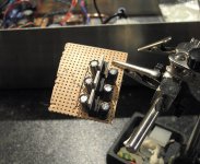
Here's my new little reg board. I should probably run each earth to the star separately, but I have joined them for the time being, to save time! I will eventually place a super reg (Audiocom or Brent's) on the digital and anologue lines, but probably not the clock reference. One needs money for such perfection...
Attachments
Hi Simon I see ur building a new external supply for your cd63/67, I found this power supply pcb that maybe an idea. Its 4 seperate +, and a single +-. Might be perfect for what your doing. Just an idea.
regulated supply schematic
regulated power supply pic
price is $10 I beleive.
regulated supply schematic
regulated power supply pic
price is $10 I beleive.
imperfectcircle said:Hi Simon I see ur building a new external supply for your cd63/67, I found this power supply pcb that maybe an idea. Its 4 seperate +, and a single +-. Might be perfect for what your doing. Just an idea.
regulated supply schematic
regulated power supply pic
price is $10 I beleive.
Hi,
That looks like it'd be really useful for someone that doesn't want to make up their own on veroboard etc. I don't mind making it all with point to point wiring. It works well enough.
I am loving this sound. I have playing "Little Girl Blue" by Diana Krall and it's sublime.
Simon
Yeah I figured it might save aot of work and time for anyone thinking of doing an external psu. This was one of the mods I wold have liked to do with my cd67, but i moved onto using my PC as my transport, much more conveinant than a single cd player I wish I could use my cd67 as a dac either connected via usb or spdif from my soundcard.
I wish I could use my cd67 as a dac either connected via usb or spdif from my soundcard.Hello most helpful people,
I've built 3 Super-Raygulators, but I'm having a problem with the output voltage (but at least I'm getting something).
I'm trying to get a 5V output, so I'm using 3.3V Zeners and the recommended diode. I should be getting 1.25+3.3+0.7 = 4.95V, but I'm only getting 4.27V (measured across ground and output. Is that the right spot?).
I went and got some 3.9V Zeners and installed them and now I'm getting 4.72V
First question (if you ignore the one above in brackets) will this output be sufficient, or do I need to get closer to 5V.
Second question if 4.72V isn't enough, the next step up for Zeners is 4.7V, which will probably the output voltage too high, so the other option is to change the 1N4148. My calculation is that I would need one with a 1V throughput. What is an appropriate part # to do that?
Below is a schematic that I drew up for component locations on the pcb. Can you tell me if I've done it wrong? (The blue wire runs across the back of the board.)
I've built 3 Super-Raygulators, but I'm having a problem with the output voltage (but at least I'm getting something
).I'm trying to get a 5V output, so I'm using 3.3V Zeners and the recommended diode. I should be getting 1.25+3.3+0.7 = 4.95V, but I'm only getting 4.27V (measured across ground and output. Is that the right spot?).
I went and got some 3.9V Zeners and installed them and now I'm getting 4.72V
First question (if you ignore the one above in brackets
) will this output be sufficient, or do I need to get closer to 5V.Second question if 4.72V isn't enough, the next step up for Zeners is 4.7V, which will probably the output voltage too high, so the other option is to change the 1N4148. My calculation is that I would need one with a 1V throughput. What is an appropriate part # to do that?
Below is a schematic that I drew up for component locations on the pcb. Can you tell me if I've done it wrong? (The blue wire runs across the back of the board.)
Making Sens of the Coax Mod on the CD67SE
Mikvous CD53? Coax mod had me trawling these forums for details for my CD67SE. This what I got and I'm confused, sorry!
Can anyone point out some more "Coax Mod details for dummies" for the Cd67SE?
Ta
k.
mikvous said:Ray, thanks for the coax mod details.Done it with great results on imaging and focus.Any other coax to be added?
Mikvous CD53? Coax mod had me trawling these forums for details for my CD67SE. This what I got and I'm confused, sorry!
By the way, there are more coax mods, does anyone have more specific info (cd67) where to put those coax?
Follow the sick and sida lines between dac and decoder. Cut track and fit coax here. Make sure CPU still gets signal though!. Also mclk (pin 4 DAC) to decoder. This carries 16mhz to decoder. I have a 63 but these are correct for 67 also. sick and sida = DAC pin 11 and 12
Is that the connection from rd14 to r104, see schematic of 67 above, can someone confirm? Yes. The 63 has a res like the 67 and a cap next to decoder. Also mclk (pin 4 DAC) to decoder. This carries 16mhz to decoder.
Coax mod on cd67se Post #2731 Where do cd67 users connect the center conductor of the coax? Straight onto pin 9 of Q101 or are there any other options?
CD53: You can replace the PCB trace that runs from junction CD01/RD14 near the DAC to junction R104/pin21 of the decoder by coax, it's the MCLK signal. Make sure you connect it to the right pin, because Marantz screwed up and used pin 22.
Tonight i did the coax mod for Dac pin 4 to decoder.RD14 was originally 220 in my cd67se, I lowered that one to 68 ohm.
placed a 1n capacitor in series. Also did the sat and slk (dac pin 11 and 12) to the cpu, didn't cut traces yet because I first wanted to listen to what it does. For these two coaxes I used a very thin silver coax wire.
COAXES. NOTE: FOR ALL COAX CABLES USE RG196. IT IS SMALL IN DIA., ONLY ABOUT .080, AND IT WILL NOT MELT
Can anyone point out some more "Coax Mod details for dummies" for the Cd67SE?
Ta
k.
YoungSC said:Hello most helpful people,
I've built 3 Super-Raygulators, but I'm having a problem with the output voltage (but at least I'm getting something
I'm trying to get a 5V output, so I'm using 3.3V Zeners and the recommended diode. I should be getting 1.25+3.3+0.7 = 4.95V, but I'm only getting 4.27V (measured across ground and output. Is that the right spot?).
I went and got some 3.9V Zeners and installed them and now I'm getting 4.72V
First question (if you ignore the one above in brackets
Second question if 4.72V isn't enough, the next step up for Zeners is 4.7V, which will probably the output voltage too high, so the other option is to change the 1N4148. My calculation is that I would need one with a 1V throughput. What is an appropriate part # to do that?
Below is a schematic that I drew up for component locations on the pcb. Can you tell me if I've done it wrong? (The blue wire runs across the back of the board.)
Diagram looks right at first glance.
Looking at your voltages, I would change the 1N4148. It may be short-circuit.
Andy
YoungSC said:Hello most helpful people,
I've built 3 Super-Raygulators, but I'm having a problem with the output voltage (but at least I'm getting something
I'm trying to get a 5V output, so I'm using 3.3V Zeners and the recommended diode. I should be getting 1.25+3.3+0.7 = 4.95V, but I'm only getting 4.27V (measured across ground and output. Is that the right spot?).
I went and got some 3.9V Zeners and installed them and now I'm getting 4.72V
First question (if you ignore the one above in brackets
Second question if 4.72V isn't enough, the next step up for Zeners is 4.7V, which will probably the output voltage too high, so the other option is to change the 1N4148. My calculation is that I would need one with a 1V throughput. What is an appropriate part # to do that?
Below is a schematic that I drew up for component locations on the pcb. Can you tell me if I've done it wrong? (The blue wire runs across the back of the board.)
Check the orientation of the diodes. You have to be able to hit 4.97v with the specified components.
Also check the orientation of the transistor. Compared to my reg. your transistor is 180 degrees off - but that can by due to the way you have build yours.
Attachments
Thanks for the reply guys.
I used this datasheet
http://www.ortodoxism.ro/datasheets/philips/BC546_547_3.pdf
for the transistor and it shows pin 1 going to the LM317 input, then I saw another data sheet with the pins the other way around .
.
Anyway, I flipped the transistor around.
I'm still getting about 4.8V.
I've measured the 3.9V Zeners and they read 2.9 V with the circuit connected. The 1N4148 reads just over 0.7V which they should. The 2 zeners and the normal diode are pointing away from each other visually and they measure that way too.
I used this datasheet
http://www.ortodoxism.ro/datasheets/philips/BC546_547_3.pdf
for the transistor and it shows pin 1 going to the LM317 input, then I saw another data sheet with the pins the other way around
.Anyway, I flipped the transistor around.
I'm still getting about 4.8V.
I've measured the 3.9V Zeners and they read 2.9 V with the circuit connected. The 1N4148 reads just over 0.7V which they should. The 2 zeners and the normal diode are pointing away from each other visually and they measure that way too.
Hi,
why have you shown two diodes in parallel?
Is that the way you installed them?
you only need one diode to adjust the zener to near your required voltage.
A zener reading 1volt under rating is either mislabelled or drawing FAR TOO LITTLE current. A red LED would be much quieter, try to find two LEDs in series that give 3.75V (maybe a red + green or two orange).
YoungSC, simplify your circuit by leaving out the gyrator (the transistor, C1 and R1) until you have a stable and usable reg.
I also have seen datasheeds saying BC547 should orientate "the wrong way", but I stick to my childhood learning. Flat side to the left, seen from the top, then you have CBE top-down.
http://www.fairchildsemi.com/ds/BC/BC547.pdf
BTW- what is your feeding voltage ?
edit - YoungSC - Andrew might have said it, your running it 5v. The zeners are drawing to little current. Try the LED trick.
I also have seen datasheeds saying BC547 should orientate "the wrong way", but I stick to my childhood learning. Flat side to the left, seen from the top, then you have CBE top-down.
http://www.fairchildsemi.com/ds/BC/BC547.pdf
BTW- what is your feeding voltage ?
edit - YoungSC - Andrew might have said it, your running it 5v.
The zeners are drawing to little current. Try the LED trick.- Home
- Source & Line
- Digital Source
- Marantz CD63 & CD67 mods list