Re: Re: Re: Re: Re: Re: CD63 Logic Problem??
I had this problem. It was the connector on the main pcb. I ran a wire from front pcb to main pcb and all is well.
A good way to test is with your DMM set it to DC volts and put probe on U116 (near connector and RY11).
If the data from the remote is getting to the main pcb the voltage will pulse/drop from +5v to 4.5v when the remote is used.
If not check pin 37 (last pin) of connector on display pcb and test again. If its there then run a wire from pin 37 to U116.
Brent
pantera6 said:
Yea, I got caught out on that switch the first time I got the player... No, I tried the switch on both internal and external... but no joy.
I'm convinced it's something to do with the front panel, but there's no way to know until I take the player apart again. Hopefully it's something really minor, like something blocking the IR sensor.
Champi
I had this problem. It was the connector on the main pcb. I ran a wire from front pcb to main pcb and all is well.
A good way to test is with your DMM set it to DC volts and put probe on U116 (near connector and RY11).
If the data from the remote is getting to the main pcb the voltage will pulse/drop from +5v to 4.5v when the remote is used.
If not check pin 37 (last pin) of connector on display pcb and test again. If its there then run a wire from pin 37 to U116.
Brent
Gooch said:
Hi Jaap
The player dose have trouble initiating it with sometimes play two or three tracks then stop. Sometimes won't play at all.
I did try the CDM12 in my other CD63 and it didn't work. And put the other CDM12 in and it work fine.
As for the current to be adjusted you need a scope for that right?
Or will a DMM work for that?
Thanks
Dave
The cdm12 laser only have a laser voltage adjust. And to be honest once you adjust this the laser life is drastically reduced.
Get that laser out and clean every part of the mech where the laser runs including the worm gear.
If its still the same then you will need a new laser.
Brent
rowemeister said:and of wiring to pins
http://www.diyaudio.com/forums/showthread.php?postid=911120
Correction:
Pin 8-9 is output and must not be connected. 10-13 is input (on FF2) and should be connected to gnd or Vcc.
Pin 1 and 4 is input (on FF1, and is active low) and should be connected to Vcc.
Fed from a Flea and injecting the 8MHz via a 47R to pin 19 of the servo.
And now on to some sonic test.
Attachments
avr300 said:
http://www.diyaudio.com/forums/showthread.php?postid=911120
Correction:
Pin 8-9 is output and must not be connected. 10-13 is input (on FF2) and should be connected to gnd or Vcc.
Pin 1 and 4 is input (on FF1, and is active low) and should be connected to Vcc.
Fed from a Flea and injecting the 8MHz via a 47R to pin 19 of the servo.
And now on to some sonic test.
Mine is
Pin 14 - Vcc
Pin 7 - gnd
FLIP FLOP 1
pin 3 - clk in
pin 5 - out
pin 6 - inverted out
pin 2 - D input
FLIP FLOP 2
pin 11 - clk in
pin 9 - out
pin 8 - inverted out
pin 12 - D input
Brent
rowemeister said:
Mine is
Pin 14 - Vcc
Pin 7 - gnd
FLIP FLOP 1
pin 3 - clk in
pin 5 - out
pin 6 - inverted out
pin 2 - D input
FLIP FLOP 2
pin 11 - clk in
pin 9 - out
pin 8 - inverted out
pin 12 - D input
Brent
Mine too, and according to your nice drawing, pin 8 and 9 is connected to gnd (ie shorten the output).
I futher have:
PINNING
PIN SYMBOL DESCRIPTION
1 1RD asynchronous reset-direct input (active LOW)
2 1D data input
3 1CP clock input (LOW-to-HIGH, edge-triggered)
4 1SD asynchronous set-direct input (active LOW)
5 1Q true flip-flop output
6 1Q complement flip-flop output
7 GND ground (0 V)
8 2Q complement flip-flop output
9 2Q true flip-flop output
10 2SD asynchronous set-direct input (active LOW)
11 2CP clock input (LOW-to-HIGH, edge-triggered)
12 2D data input
13 2RD asynchronous reset-direct input (active LOW)
14 VCC positive supply voltage
where 10-13 is input.
Now after a night with the reclocked servo I must admit, Brent is right - this mod works.
Krall now sounds so sweet on "life in Paris". You can now really hear all the mechanical "noise" inside her piano, somewhat scaring.
I also think that the pace has improved. It really stands up to the task now.
Big
Krall now sounds so sweet on "life in Paris". You can now really hear all the mechanical "noise" inside her piano, somewhat scaring.
I also think that the pace has improved. It really stands up to the task now.
Big
Re: Re: Re: Re: Re: Re: Re: CD63 Logic Problem??
Thanks Brent I wiggled the flex cable to the front panel and re-inserted it and that seemed to do the trick :0 Remote is now operational!
Champi
rowemeister said:
I had this problem. It was the connector on the main pcb. I ran a wire from front pcb to main pcb and all is well.
A good way to test is with your DMM set it to DC volts and put probe on U116 (near connector and RY11).
If the data from the remote is getting to the main pcb the voltage will pulse/drop from +5v to 4.5v when the remote is used.
If not check pin 37 (last pin) of connector on display pcb and test again. If its there then run a wire from pin 37 to U116.
Brent
Thanks Brent
I wiggled the flex cable to the front panel and re-inserted it and that seemed to do the trick :0 Remote is now operational!Champi
Servo Clock Mod
Now that my player is back to "normal" I'm ready to take on the much talked about servo clock mod, so for those of you who've done this and have seen the benifits, I've got some specific questions that perhaps others also wanting to do this mod may have:
1) Since I don't have an external clock (still running the standard crystal), where can I tap the 16.9344 MHz clock feed for the flip-flop? Would pin 4 of the DAC be the place to do this.... after C521?
2) On the Servo side, I understand that the 8.43 MHz output from the flip-flop should be connected to pin 19 of the servo chip. Do you have to take out both R126 and X101 when connecting to pin 19... or just R126 and leave X101 be?
3) The 100 ohm resistor that's added in series with the 16.9344 MHz feed, is that meant to be just before pin 19 of the servo (like a termination resistor) or closer to where the clock feed is tapped off the DAC?
4) Should any other termination (capacitance or resistance) be added to the 8.43 MHz feed from the flip-flop to pin 19 of the servo to eliminate some of the interference problems Brent was initially having?
5) Placement - how long (cm?) should the coax be from the flip-flop's 8.46 MHz out to pin 19 of the Servo chip to eliminate the tracking problems?
Many Thanks guys... I'm really looking forward to reporting on how this mod sounds...as it seems to be a "major" step forward in the improvement of the 63!
Champi
rowemeister said:
Mine is
Pin 14 - Vcc
Pin 7 - gnd
FLIP FLOP 1
pin 3 - clk in
pin 5 - out
pin 6 - inverted out
pin 2 - D input
FLIP FLOP 2
pin 11 - clk in
pin 9 - out
pin 8 - inverted out
pin 12 - D input
Brent
Now that my player is back to "normal"
I'm ready to take on the much talked about servo clock mod, so for those of you who've done this and have seen the benifits, I've got some specific questions that perhaps others also wanting to do this mod may have:1) Since I don't have an external clock (still running the standard crystal), where can I tap the 16.9344 MHz clock feed for the flip-flop? Would pin 4 of the DAC be the place to do this.... after C521?
2) On the Servo side, I understand that the 8.43 MHz output from the flip-flop should be connected to pin 19 of the servo chip. Do you have to take out both R126 and X101 when connecting to pin 19... or just R126 and leave X101 be?
3) The 100 ohm resistor that's added in series with the 16.9344 MHz feed, is that meant to be just before pin 19 of the servo (like a termination resistor) or closer to where the clock feed is tapped off the DAC?
4) Should any other termination (capacitance or resistance) be added to the 8.43 MHz feed from the flip-flop to pin 19 of the servo to eliminate some of the interference problems Brent was initially having?
5) Placement - how long (cm?) should the coax be from the flip-flop's 8.46 MHz out to pin 19 of the Servo chip to eliminate the tracking problems?
Many Thanks guys... I'm really looking forward to reporting on how this mod sounds...as it seems to be a "major" step forward in the improvement of the 63!
Champi
avr300 said:Now after a night with the reclocked servo I must admit, Brent is right - this mod works.
Krall now sounds so sweet on "life in Paris". You can now really hear all the mechanical "noise" inside her piano, somewhat scaring.
I also think that the pace has improved. It really stands up to the task now.
Big
I knew you would be happy with it Brent
Re: Servo Clock Mod
1) You need a clock mate. Its one of the best mods too!
2) Remove both
3) I put it on the output of the clock
4) No. The prblems I had was with the gnd wire (had a break in it) and also the lenght of the coax from servo clock to servo. I found mounting it right up to the servo was best.
5) I found mounting it right up to the servo was best.
Brent
pantera6 said:
Now that my player is back to "normal"
1) Since I don't have an external clock (still running the standard crystal), where can I tap the 16.9344 MHz clock feed for the flip-flop? Would pin 4 of the DAC be the place to do this.... after C521?
2) On the Servo side, I understand that the 8.43 MHz output from the flip-flop should be connected to pin 19 of the servo chip. Do you have to take out both R126 and X101 when connecting to pin 19... or just R126 and leave X101 be?
3) The 100 ohm resistor that's added in series with the 16.9344 MHz feed, is that meant to be just before pin 19 of the servo (like a termination resistor) or closer to where the clock feed is tapped off the DAC?
4) Should any other termination (capacitance or resistance) be added to the 8.43 MHz feed from the flip-flop to pin 19 of the servo to eliminate some of the interference problems Brent was initially having?
5) Placement - how long (cm?) should the coax be from the flip-flop's 8.46 MHz out to pin 19 of the Servo chip to eliminate the tracking problems?
Many Thanks guys... I'm really looking forward to reporting on how this mod sounds...as it seems to be a "major" step forward in the improvement of the 63!
Champi
1) You need a clock mate. Its one of the best mods too!
2) Remove both
3) I put it on the output of the clock
4) No. The prblems I had was with the gnd wire (had a break in it) and also the lenght of the coax from servo clock to servo. I found mounting it right up to the servo was best.
5) I found mounting it right up to the servo was best.
Brent
Re: Servo Clock Mod
Like Brent said, I wouldn't bother doing this without a low jitter clock. That is the main goal of this mod, feeding the servo the right food.
I didn't have any problems with tracking, I'm using a 47R between the ff and pin19 of the servo.
Brent, do you ack. the error on your drawing? If you have wired the ff as shown, perhaps that's the reason for your tracking problems. Undefined inputs and shortened output. As bad as it gets
pantera6 said:
Now that my player is back to "normal"
1) Since I don't have an external clock (still running the standard crystal), where can I tap the 16.9344 MHz clock feed for the flip-flop? Would pin 4 of the DAC be the place to do this.... after C521?
2) On the Servo side, I understand that the 8.43 MHz output from the flip-flop should be connected to pin 19 of the servo chip. Do you have to take out both R126 and X101 when connecting to pin 19... or just R126 and leave X101 be?
3) The 100 ohm resistor that's added in series with the 16.9344 MHz feed, is that meant to be just before pin 19 of the servo (like a termination resistor) or closer to where the clock feed is tapped off the DAC?
4) Should any other termination (capacitance or resistance) be added to the 8.43 MHz feed from the flip-flop to pin 19 of the servo to eliminate some of the interference problems Brent was initially having?
5) Placement - how long (cm?) should the coax be from the flip-flop's 8.46 MHz out to pin 19 of the Servo chip to eliminate the tracking problems?
Many Thanks guys... I'm really looking forward to reporting on how this mod sounds...as it seems to be a "major" step forward in the improvement of the 63!
Champi
Like Brent said, I wouldn't bother doing this without a low jitter clock. That is the main goal of this mod, feeding the servo the right food.
I didn't have any problems with tracking, I'm using a 47R between the ff and pin19 of the servo.
Brent, do you ack. the error on your drawing? If you have wired the ff as shown, perhaps that's the reason for your tracking problems. Undefined inputs and shortened output. As bad as it gets
Re: Re: Servo Clock Mod
I did change mine last friday but have not updated the pic.
How can I change it?
The ic runs warmer now with all the pins wired.
Brent
avr300 said:
Like Brent said, I wouldn't bother doing this without a low jitter clock. That is the main goal of this mod, feeding the servo the right food.
I didn't have any problems with tracking, I'm using a 47R between the ff and pin19 of the servo.
Brent, do you ack. the error on your drawing? If you have wired the ff as shown, perhaps that's the reason for your tracking problems. Undefined inputs and shortened output. As bad as it gets
I did change mine last friday but have not updated the pic.
How can I change it?
The ic runs warmer now with all the pins wired.
Brent
gy21 said:Does anyone know what the tolerance is for the Filter capacitors c605/606 and CD21-24 that are default in the cd67se?
So what is currently in there tolerance wise?
Nope LOL
I would guess at 20%
Brent
rowemeister said:
Nope LOL
I would guess at 20%
Brent
Hi.
In the CD63, C605 / C606 are :-
P116 Capacitors ( Common )
Plastic Film Capacitor
One-Way Type, Myler +- 5%, 50v
CD21 - CD24 are Film 120pF, 100v +-5%
Andy
avr300 said:
http://www.diyaudio.com/forums/showthread.php?postid=911120
Correction:
Pin 8-9 is output and must not be connected. 10-13 is input (on FF2) and should be connected to gnd or Vcc.
Pin 1 and 4 is input (on FF1, and is active low) and should be connected to Vcc.
Fed from a Flea and injecting the 8MHz via a 47R to pin 19 of the servo.
And now on to some sonic test.
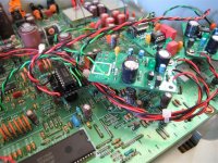
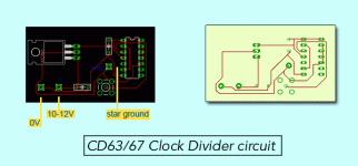
Maybe this small board can be of help. It consists of a 7805 reg with two accompanying caps (.33 and .1uF), a SMB jack and the 74LS74.
The board can be fitted in the hole above C142 (on the left side).
As mentioned in an earlier post by Allen, the reg gets its ground from star ground. Maybe someone can scrutinize the connections, as there was a small dispute about wiring.
Regards, Jaap
Attachments
Re: Re: Servo Clock Mod
Thanks Guys.... looks like a proper dedicated clock is the next stage mod for me then. In the true spirit of DIY, I don't want to invest in a clock that's 3 times more expensive than my CD63... so I might try the Tent XO module and the Flea circuit board and build my own power supply for the Flea. It will take me a while to get the parts from Europe though
The other option is to get an LClock X03 from the dealers in Australia (considerably cheaper than the Audiocom Super Clock). Here's a couple more questions for you all:
1) Given the price differential between the Tent XO + Flea and the LClock XO3+ LClock Power supply, would I notice a significant difference between the two, as in the LClock XO3 being much better than the Tent XO? I know these questions have been debated in these forums time and again... just wondering if anyone has some experience directly relating to a CD63.
2) I have implemented Martin Clark's Acoustica Clock hack... and it did make a significant difference, especially when fed by a LM317 pre reg and LT1086 5V reg. I'm using silver mica caps, but the crystal is still stock (though I have a low PPM crystal waiting to be put in). I guess the real question is... would a dedicated clock, either the Tent XO/Flea or LClock XO3 be significantly better than my current configuration?
Interested in hearing your opinions.
Thanks once again for the useful feedback
Champi
rowemeister said:
1) You need a clock mate. Its one of the best mods too!
2) Remove both
3) I put it on the output of the clock
4) No. The prblems I had was with the gnd wire (had a break in it) and also the lenght of the coax from servo clock to servo. I found mounting it right up to the servo was best.
5) I found mounting it right up to the servo was best.
Brent
avr300 said:
Like Brent said, I wouldn't bother doing this without a low jitter clock. That is the main goal of this mod, feeding the servo the right food.
I didn't have any problems with tracking, I'm using a 47R between the ff and pin19 of the servo.
Brent, do you ack. the error on your drawing? If you have wired the ff as shown, perhaps that's the reason for your tracking problems. Undefined inputs and shortened output. As bad as it gets
Thanks Guys.... looks like a proper dedicated clock is the next stage mod for me then. In the true spirit of DIY, I don't want to invest in a clock that's 3 times more expensive than my CD63... so I might try the Tent XO module and the Flea circuit board and build my own power supply for the Flea. It will take me a while to get the parts from Europe though
The other option is to get an LClock X03 from the dealers in Australia (considerably cheaper than the Audiocom Super Clock). Here's a couple more questions for you all:
1) Given the price differential between the Tent XO + Flea and the LClock XO3+ LClock Power supply, would I notice a significant difference between the two, as in the LClock XO3 being much better than the Tent XO? I know these questions have been debated in these forums time and again... just wondering if anyone has some experience directly relating to a CD63.
2) I have implemented Martin Clark's Acoustica Clock hack... and it did make a significant difference, especially when fed by a LM317 pre reg and LT1086 5V reg. I'm using silver mica caps, but the crystal is still stock (though I have a low PPM crystal waiting to be put in). I guess the real question is... would a dedicated clock, either the Tent XO/Flea or LClock XO3 be significantly better than my current configuration?
Interested in hearing your opinions.
Thanks once again for the useful feedback
Champi
Re: Re: Re: Servo Clock Mod
Champi
Checkout this clock card hagclock This is what I have it won't cost arm & leg I felt the same way you do that's why I never bought one years ago. Jim is a great guy and ships world wide. I even have some left over parts from building mine I could send you if that helps.
Regards,
Dave
pantera6 said:
Thanks Guys.... looks like a proper dedicated clock is the next stage mod for me then. In the true spirit of DIY, I don't want to invest in a clock that's 3 times more expensive than my CD63... so I might try the Tent XO module and the Flea circuit board and build my own power supply for the Flea. It will take me a while to get the parts from Europe though
The other option is to get an LClock X03 from the dealers in Australia (considerably cheaper than the Audiocom Super Clock). Here's a couple more questions for you all:
1) Given the price differential between the Tent XO + Flea and the LClock XO3+ LClock Power supply, would I notice a significant difference between the two, as in the LClock XO3 being much better than the Tent XO? I know these questions have been debated in these forums time and again... just wondering if anyone has some experience directly relating to a CD63.
2) I have implemented Martin Clark's Acoustica Clock hack... and it did make a significant difference, especially when fed by a LM317 pre reg and LT1086 5V reg. I'm using silver mica caps, but the crystal is still stock (though I have a low PPM crystal waiting to be put in). I guess the real question is... would a dedicated clock, either the Tent XO/Flea or LClock XO3 be significantly better than my current configuration?
Interested in hearing your opinions.
Thanks once again for the useful feedback
Champi
Champi
Checkout this clock card hagclock This is what I have it won't cost arm & leg I felt the same way you do that's why I never bought one years ago. Jim is a great guy and ships world wide. I even have some left over parts from building mine I could send you if that helps.
Regards,
Dave
Re: Re: Re: Servo Clock Mod
Personally I would always got for a good clock! In the UK fitting a clock (at ebay prices) you will get your money back when selling the cdp. Also you would be able to use it in another player.
For me I have moddified mine so much I would have to spend a lot of money on a player to better it so ill probs keep it for ever lol.
Also make sure the clock will happily run 2 or more ics. I checked with Audiocom and they told me it would.
Also I tried to get the servo clock mod to work running off a crystal and its a no go, it can be done but there will be more work involved and not really any benefit.
I fit 5ppm crystals to players I mod where im not fitting super clock and they do improve the audio. I would say its half way between standard 50ppm crystal and audiocom clock.
Can you not get a Audiocom clock on ebay from UK.
http://cgi.ebay.co.uk/AUDIOCOM-SUPE...QitemZ9728848303QQcategoryZ3272QQcmdZViewItem
Brent
pantera6 said:
Thanks Guys.... looks like a proper dedicated clock is the next stage mod for me then. In the true spirit of DIY, I don't want to invest in a clock that's 3 times more expensive than my CD63... so I might try the Tent XO module and the Flea circuit board and build my own power supply for the Flea. It will take me a while to get the parts from Europe though
The other option is to get an LClock X03 from the dealers in Australia (considerably cheaper than the Audiocom Super Clock). Here's a couple more questions for you all:
1) Given the price differential between the Tent XO + Flea and the LClock XO3+ LClock Power supply, would I notice a significant difference between the two, as in the LClock XO3 being much better than the Tent XO? I know these questions have been debated in these forums time and again... just wondering if anyone has some experience directly relating to a CD63.
2) I have implemented Martin Clark's Acoustica Clock hack... and it did make a significant difference, especially when fed by a LM317 pre reg and LT1086 5V reg. I'm using silver mica caps, but the crystal is still stock (though I have a low PPM crystal waiting to be put in). I guess the real question is... would a dedicated clock, either the Tent XO/Flea or LClock XO3 be significantly better than my current configuration?
Interested in hearing your opinions.
Thanks once again for the useful feedback
Champi
Personally I would always got for a good clock! In the UK fitting a clock (at ebay prices) you will get your money back when selling the cdp. Also you would be able to use it in another player.
For me I have moddified mine so much I would have to spend a lot of money on a player to better it so ill probs keep it for ever lol.
Also make sure the clock will happily run 2 or more ics. I checked with Audiocom and they told me it would.
Also I tried to get the servo clock mod to work running off a crystal and its a no go, it can be done but there will be more work involved and not really any benefit.
I fit 5ppm crystals to players I mod where im not fitting super clock and they do improve the audio. I would say its half way between standard 50ppm crystal and audiocom clock.
Can you not get a Audiocom clock on ebay from UK.
http://cgi.ebay.co.uk/AUDIOCOM-SUPE...QitemZ9728848303QQcategoryZ3272QQcmdZViewItem
Brent
- Home
- Source & Line
- Digital Source
- Marantz CD63 & CD67 mods list