1.5A will be fine. Regulating the servo supply will make the servo's a bit more responsive, because the voltage doesn't drop anymore under load.
The voltages at pins 7 and 8 are a typo in the schematic. Notice how pin 8 is connected to pin 1? They can't be 0V and 2.5V at the same time ;-)
The voltages at pins 7 and 8 are a typo in the schematic. Notice how pin 8 is connected to pin 1? They can't be 0V and 2.5V at the same time ;-)
Hi Ray,
So my problem might not be Q105? Brakspear swapped out Q105 when the input pins were at 0 and fixed the servo. Do you think I should swap it anyway, or would I be wasting my time? I am just not sure where to look next!
Henry
So my problem might not be Q105? Brakspear swapped out Q105 when the input pins were at 0 and fixed the servo. Do you think I should swap it anyway, or would I be wasting my time? I am just not sure where to look next!
After a lot of testing and swapping bits I found that Q105 was half dead - pins 7&8 (laser diode) were zero volts, although 5&6 were OK at 2.5V. All surounding components checked out OK so I swapped the opamp out with ones from my old board and eventually found one that still worked. I now have a working servo section, player reads & plays disks and all the waveforms look good - just the dead DAC to fix.
Henry
Last edited:
Hi,
both the disc motor and laser are not functioning on my CD63:
Is it more likely that the laser is the primary cause of the malfunction. In other words: if the laser fails then the motor will not run.
Alternatively, if the disc motor fails to spin then the laser will not turn on.
Does anyone know which is true?
Thanks! Henry
Looking back at the results you got in service mode, you said in P01 you got slow focussing ie laser head moves up & down at normal speed. P02 gave fast focussing - I assume that means the laser head chattering up & down quickly, yes? Afaik, if the laser doesn't focus, the signal to start spinning the disc won't be sent, so the disc motor won't run.
When I replaced Q105 I had no output voltage to the laser diode and pins 7&8 always seemed to stay low - you've tested at R136 and found 5V, so Q105 is probably ok. The dreaded ribbon cable takes power to the laser - have you checked both sockets for cracked joints & tried using a needle to bend the contacts gently if they're looking squashed? (unless you've replaced it, not sure what mods you've done!) If you can, try picking the laser voltage up on the RF Amp pcb trace to be sure.
Using some regs on the supplies to these chips is well worth it, especially if you're currently running close to the 40V limit between the rails, but I'd sort this problem out first before adding more bits to test. It's not unheard of for new lasers to be duff - might be worth trying to get a replacement for the new one.
Hi Brakespear 75, yes - the laser moves up and down, so I will focus on a laser fault first. The mods are most of those on Ray's list and toroid transformers. I don't think it is the laser itself as I have tried a new one and a spare that I have. I will check the voltage at the laser next as you suggest. Thanks for your advice!!! Henry
Hi,
I am so far (until today) "passive reader" of diyaudio. But so far succesfull...
I did Marantz PM 66 Ki modifications with all the caps replacement, bigger heatsinks+higher power transistors, dual trafos, etc...
Result: massive and fast bass and at all very much different amplifier comparing to factory design...
Now I did very intensive upgrade to my 20-years old CD 67 mk II:
- replaced all the caps in psu (Mundorf+nichicon + SMD ceramic in parallel for each electrolytic cap)
- +/- 12V regulators based on LM317/337
- +5V regulators separately for analogue/digital part of DAC based on LM317
- external "super clock" for DAC with dedicated PSU
- mains filter
- Bessel LPF - based on 1% silver mica caps + 0.1% SMD resistors
- for opamps I target to use Burson v5...
- i did also muting device based on relays
Most of mods based on Ray's WWW page which I followed many many times...
http://www.raylectronics.nl/index_en.html
Now I'm in trouble:
- all PSU voltages are Ok
- muting relays works excellent
- clock for DAC is OK
but... no sound :-(
PWM outputs from DAC seems to be OK (switching 0 - 5 V)
Eye pattern from Decoder seems acceptable (approx 1.5V peak-to-peak)
But at the OPAM pin1 there is only approx 80-100mV peak-peak that can be measured...
I have all checked on the multimeter and/or scope...
Either:
- no proper signal from DAC...
or
- no signal from Decoder so DAC effectively converts nothing...
Does anyone experienced such problem ?
Thanks for your advice! Marcin
- +5V regulators separately for analogue/digital part of DAC based on LM317
I Wonder if separate +5VDC LM317 for DAC AVdd and DVdd could latch-up the chip at power on...?
(but pwm outputs seems to be OK...
May be that some protection diodes shall be used between PSU regulators to avoid to big voltage difference at power on...
Any help really appreciated...
I Wonder if separate +5VDC LM317 for DAC AVdd and DVdd could latch-up the chip at power on...?
QUOTE]
Just to update on the topic. It took me hours to find the problem source...
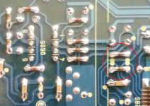
Shame on me! Stupid soldering mistake. Mainly the reason was the SMD and installation on the opposite side of pcb (no markings). That's my excuse only... The RDxx (actually DAC outputs resistors) were altered 90 degrees (!). Fortunately DAC is fine and working. It also looks like dual regulators +5V did not hurt the DAC.
Hi,
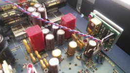
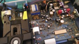
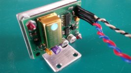
I attached some photos of modifications. SMD-mistake shows exactly where was the problem. Currently separate AVdd and DVdd regulators for DAC are removed. DAC is working on standard factory +5VDC. Now its time to enjoy music for a while...
Regards
Marcin
I attached some photos of modifications. SMD-mistake shows exactly where was the problem. Currently separate AVdd and DVdd regulators for DAC are removed. DAC is working on standard factory +5VDC. Now its time to enjoy music for a while...
Regards
Marcin
Attachments
Hi Everyone,
I do hope someone could kindly guide me in regards of two topics.
1.
Multiple power supply pins in servo/decoder and DAC:
SM5872BS datasheet page 5:
„All power supply pins (VDD and VSS) must be connected to the same extermal power supply unit”
SAA7372 datasheet page 6:
„All supply pins must be connected to the same external power supply voltage”
Does it mean all pins from the same regulator? (I know from this forum about multi-reg implementations done by experts: Fidelity Audio or 6h5c)
Is there any risk with multiple regs for single chip?
2.
At power on CD player should read TOC from disc even if disc was already inside the tray. It is not working. Not always. By fast switching power-off/power-on the disc is detected and TOC is visible. (Normal operation: power-on, tray-open, tray-close - this is always OK). Have You ever notice such behaviour? I think the reason could be to short RESET time at power on (RC delay with RF03+CF03). Either "old" CF03 lost parametres or the entire CD (bigger PSU caps ?) require a bit longer delay for microC and servo/decoder. I will check the cap and/or replace 100kom RF03 with 200k.
Regards/Marcin
hi,
got a problem with an aging sa7001ki. the display stays rather dark. in a dark room text is visible and scrolling but at day-time it is barely readable. does any of you know a fix? is it the display itself or power supply? perhaps some capacitor?
Did you have the “Remote Controller RC7001SA“?
Press the “Display“ button several times.
Here did you get the service manual for Marantz SA7001KI:
Ray's Audio Page
Ray's Audio Page - en
Did you have the “Remote Controller RC7001SA“?
Press the “Display“ button several times.
Here did you get the service manual for Marantz SA7001KI:
Ray's Audio Page
Ray's Audio Page - en
Thanks for your reply. I tried pushing the display button on the remote and the front until display is off and a red signal is shown. Even in the brightest setting the display is barely readable. The service manual shows 2 AC 4.3 voltages and a -26 voltage. I don't know much about such a display and which voltages control the brightness.
Hello,
My last CD player had the problem with the visibility of the control screen getting darker and darker over several years. Did some research on line and found that the problem was a known one caused by the display used in it.
Contacted the company and was told there was nothing to be done for it.
(AH! Njoe Tjoeb 4000 CD player)
Player was decent one but company pretty much went away and has no support. Quite possible some other makers units used this display as well. FWIW.
Would suggest contacting the company tech support (and doing a search online as well) - to see if this is a known problem for your player.
Regards,
Greg
Thanks for your reply. I tried pushing the display button on the remote and the front until display is off and a red signal is shown. Even in the brightest setting the display is barely readable. The service manual shows 2 AC 4.3 voltages and a -26 voltage. I don't know much about such a display and which voltages control the brightness.
Please contact Ray possibly he could help you. Such as searching for spare part.
As far as I know, the display like basically an magic eye tube like an EM84.
AC is for the filament, DC for anode/cathode voltage.
Tubes could lost the filament coating, display tubes could lost the fluorescence coating too.
Is Ray still around here? Might PM him. Like me, he is from the Netherlands I think.
Yes, the voltages on all three pins are always the same. The driver opamp is configured as a voltage follower or buffer, by connecting the inverting or '-' input to the output. So if the non-inverting input becomes high (5V), the output also goes high.
Hi Ray,
I am Dirk from the Netherlands. The display in my SA 7001 KI is losing its brightness. Is the display itself faulty or is it the power supply. What is usually causing the degradation in brightness? Are there any spare parts available?
BTW, the unit has not been used for several years but still fully functional. I can still see text scrolling but I need to look hard.
- Home
- Source & Line
- Digital Source
- Marantz CD63 & CD67 mods list