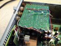
After a lot of testing and swapping bits I found that Q105 was half dead - pins 7&8 (laser diode) were zero volts, although 5&6 were OK at 2.5V. All surounding components checked out OK so I swapped the opamp out with ones from my old board and eventually found one that still worked. I now have a working servo section, player reads & plays disks and all the waveforms look good - just the dead DAC to fix.
Bypass capacitors
Hi, i'd like to replace opamp on my Marantz CD63 and i am following the guidelines described on Marantz CD 63/67
I don't understant were to put bypass film capacitors as described in the link.
Could anyone post a picture of where they must be placed (if i undestood on the other side of the PCB board).
Thanks in advance,
bypass capacitors
Hi, i'm trying to do some mods on my marantz CD53SE based on the guidelines provided on the link Marantz CD 63/67. I can't guess where to place bypass film capacitors.
Is there anyone can post a picture where they must be applied on the pcb ?
if i undestood they must be placed underside.
Thanks in advance
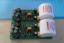
Now i have wilma 22nf capacitors ... i'am trying to guess from various pictures found on the web how to place across the electrolytic capacitors.
From what i guess is it correct to apply in the rear pcb accross electrolytic + / - connection or should i have to apply the bypass from the positive pole of the electrolitic capacitor to another point on the ground in the pcb ?
From what i guess is it correct to apply in the rear pcb accross electrolytic + / - connection or should i have to apply the bypass from the positive pole of the electrolitic capacitor to another point on the ground in the pcb ?
I don't understant were to put bypass film capacitors as described in the link.
Could anyone post a picture of where they must be placed (if i undestood on the other side of the PCB board).
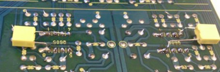
In my modest CD-67 mod I placed the 100nF rail decoupling capacitors under the opamps.
As I have understood these caps have to be soldered as near to the opamp as possible.
The film caps over lytics are something that I have never tried - I do not think I can hear their presence.
Attachments
thank you so much madis64!
You are welcome
")
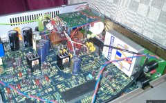
However I would say that modding the opamp stages was only an intermediate step to the final solution with Ray's DOS (with signal attenuated to the level of the rest of my "old" audio gear so that I do not to wrestle too much with my tube amp volume knob when changing the sources).
Attachments
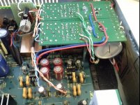
One of the first steps you take should be fixing the power sources (to whatever fancy level you decide).
Then you can spend time on listening to different opamps.
Then you should replace the clock.
At one point you probably decide to stop ;-)
You could also measure your Marantz and other players with RMAA - just to see if you can find any changes in numbers and graphs.
And more than half of my music collection is on vinyl too
Hi Everyone,
Hope someone could kindly guide me here in regards to CD63 KI troubleshooting, that I own for a good while and have modified slightly, but now has developed a problem I can't seem to trace down.
Before I continue, it looks like this problem was developing over time and until unit is barely usable now.
What happens is, at times I need to turn the unit on and off few times before the display says anything at all. Once it does turn on however, everything works flawlessly until a random point in play back (could be half disc or never) the unit would simply freeze completely with random characters lit on the display and would not respond to any buttons. The spindle turns back and forth when this happens. After that I need to switch it off and on few times before it starts up properly.
It sounds like an MCU fault... I did replace the display ribbon cable and sockets with a usual multiwire ribbon cable soldered directly sometime in the past.
I checked the MCU resonator with an oscilloscope and it reads a little low, about 3V in amplitude on one pin and maybe 1V with 2V DC offset on the other, which is different to what manual says, 5V and 4.6V with no offset. I replaced the resonator with exact same part, but measurements are same. Is controller giving up?
Any advice?
Many thanks
In my modest CD-67 mod I placed the 100nF rail decoupling capacitors under the opamps.
As I have understood these caps have to be soldered as near to the opamp as possible.
The film caps over lytics are something that I have never tried - I do not think I can hear their presence.
I have applied a decoupling capacitor between pin 4 and 8 soldered on top of the opamp lm6172. I tried one first. The opamp now is fried. Am I missing something or should I decouple v+ and v- to somewhere else point?
Last edited:
I have never soldered any caps directly to opamps - my way is to solder them below the board (and use sockets for opamp rolling).
LM6172 did not stay on my like-list (after testing it out) also ...
Edit: 0,22nF translates to 220pF - are you sure about the capacity?
LM6172 did not stay on my like-list (after testing it out) also ...
Edit: 0,22nF translates to 220pF - are you sure about the capacity?
Last edited:
I have never soldered any caps directly to opamps - my way is to solder them below the board (and use sockets for opamp rolling).
LM6172 did not stay on my like-list (after testing it out) also ...
Edit: 0,22nF translates to 220pF - are you sure about the capacity?
Sorry I mean 0,022uf, is this correct?
Sorry I mean 0,022uf, is this correct?
Correct is what you used - so what capacitor did you use?
This way or another, I have used 100...200nF caps (mostly 100nF) for this purpose.
Correct is what you used - so what capacitor did you use?
This way or another, I have used 100...200nF caps (mostly 100nF) for this purpose.
I don't remember the brand. I've took them from farnell, they are blue with 63v
What opamp do you suggest? Opa2134?
I am using sockets but when I have applied the capacitor no sound was coming from that channel. After desoldering capacitor opamp was dead
You wrote that you applied the cap on top of the opamp - the only way to do it is to solder it directly to the opamp - or?
- Home
- Source & Line
- Digital Source
- Marantz CD63 & CD67 mods list