Agreed, this thread is awesome!!
Thanks, UV101, it looks like I went one step too far and totally separated digital and analogue grounds, resulting in the 'floating ground' problem you describe. I have now re-connected the grounds at the tx via a link wire with ferrite beads on which should be equivalent to the suggested low ohm inductor but like I said, the player is still dead.
Looking back at the way I traced the ground circuits it looks like the input side of the DAC would have been referenced to the digital ground, whilst output side was referenced to analogue ground. Given that analoge ground was +4.25V higher than digital, I guess it's the DAC chip I've fried Would that fit with getting no audio out, just very low volume white noise?
Are there any other voltages I can test to confirm that it's the DAC that's dead?
Assuming I get past this (probably by buying a 'sacrificial' cd63 off ebay for the chips), where is the best place to have the connection between the digital and analogue grounds in order to minimise digital noise on the analogue circuit?
Thanks, UV101, it looks like I went one step too far and totally separated digital and analogue grounds, resulting in the 'floating ground' problem you describe. I have now re-connected the grounds at the tx via a link wire with ferrite beads on which should be equivalent to the suggested low ohm inductor but like I said, the player is still dead.
Looking back at the way I traced the ground circuits it looks like the input side of the DAC would have been referenced to the digital ground, whilst output side was referenced to analogue ground. Given that analoge ground was +4.25V higher than digital, I guess it's the DAC chip I've fried
Would that fit with getting no audio out, just very low volume white noise?Are there any other voltages I can test to confirm that it's the DAC that's dead?
Assuming I get past this (probably by buying a 'sacrificial' cd63 off ebay for the chips), where is the best place to have the connection between the digital and analogue grounds in order to minimise digital noise on the analogue circuit?
Looks like a fried DAC... It got a floating power supply I guess.
First, I would check if all the supply-voltages are there. You can check if the DAC is still alive by checking the outputs with a DMM. It's pins 18, 20, 23 and 25. Normally, there's a 5V/50% duty-cycle square wave present there, and if you measure it with a DMM this translates to 2.5V DC. If you have a scope, you can check the square wave of course
First, I would check if all the supply-voltages are there. You can check if the DAC is still alive by checking the outputs with a DMM. It's pins 18, 20, 23 and 25. Normally, there's a 5V/50% duty-cycle square wave present there, and if you measure it with a DMM this translates to 2.5V DC. If you have a scope, you can check the square wave of course
Great idea, you're all invited! If you bring your gear, I'll handle the beer!
That would be really something, a DIY Audio party in my backyard
Did someone mention a DIY party?!?
I am in - with a few cases of Heineken.... when should I book my tickets from Australia?

Agreed, this thread is awesome!!
Thanks, UV101, it looks like I went one step too far and totally separated digital and analogue grounds, resulting in the 'floating ground' problem you describe. I have now re-connected the grounds at the tx via a link wire with ferrite beads on which should be equivalent to the suggested low ohm inductor but like I said, the player is still dead.
Looking back at the way I traced the ground circuits it looks like the input side of the DAC would have been referenced to the digital ground, whilst output side was referenced to analogue ground. Given that analoge ground was +4.25V higher than digital, I guess it's the DAC chip I've fried
Are there any other voltages I can test to confirm that it's the DAC that's dead?
Assuming I get past this (probably by buying a 'sacrificial' cd63 off ebay for the chips), where is the best place to have the connection between the digital and analogue grounds in order to minimise digital noise on the analogue circuit?
If you are still after an SM5872 DAC chip, let me know - i had a few spare chips (new and used pulls) that I have hung onto as I have also fried a dac chip during mods.

Did someone mention a DIY party?!?
I am in - with a few cases of Heineken.... when should I book my tickets from Australia?
Yes, at my place! You're invited!
I was thinking of next month, saturday 17th september? I'll take care of the Heineken, wouldn't want to burden you with that as well, besides the ticket...
Well I've checked the voltages - all the supplies are present and measure 5.08V on my meter so that's fine. Trouble is, the PCM outputs measure 5.08V on my dmm too - if these are meant to be 2.5V then I guess that confirms the fried DAC.
I went round the board to check all the chip supplies and everything now measures fine so at least the grounding is sorted again. I actually have another pcb myself so I'll swap the DAC chips over and hope that restores sound (and sanity!). Not overly hopeful though - that spare pcb is the one I killed the servo amps on, and I don't know if the carnage extended to other circuits...
Yes, I know, I'm going to get a reputation as a '63 killer, but what else do you do with chips except fry them?!
Yep, i'm afraid it's dead... 
However, it could be that the clock signal is missing, I think the outputs show the same behaviour if MCLK is not present. So if you're shure your clock is working properly, or you still have the original crystal in there, then it's for certain.
The servo amps are far away from the DAC, so there is good hope your spare DAC is still working!
Ray
Last edited:
I've now swapped the DAC chips and sadly the new one is no more musical than the last - in fact less so, as I now have a loud mains hum as well as low level white noise on the output.
I think the clock is fine - I'm using a Flea clock powered off C803 so input power and earth connection at the DAC earth plane would both have been referenced to analogue supply. Certainly the green LED lights up ok, is there anything else I can check without a scope to make sure?
If the clock is OK, I think I'm in the market for a spare DAC chip...
Hm, bummer...
You can check the clock the same way as you did the DAC outputs: with a DMM there should be around 2.5V DC at the output, a sign that there is a 5V square wave present.
Before swapping more parts, your player should be checked with an oscilloscope. That way you can make sure if the three digital signals from the decoder are all present, just in case.
I've been seriously considering getting a scope and this latest mistake has made up my mind - just got a Tektronix 2213 60MHz off ebay for £66 including probes and delivery. I hope it's in as good a condition as the seller says - will find out on Monday and then I can check everything properly!
As always, many thanks for the advice.
As always, many thanks for the advice.
The oscilloscope arrived and works perfectly, at least as far as the bits I know how to use!
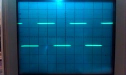
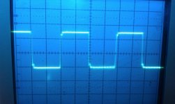
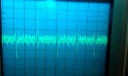
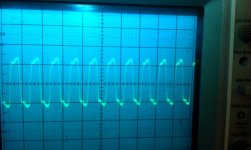
I've taken some pics of the signals I've got; the Flea clock, SCLK and WCLK look good but Data is just low level noise. That said, the state of the DAC chip is such that I don't think the processor is seeing the correct info so the CD doesn't recognise the disk and therefore doesn't enter play mode, so perhaps the Data signal is missing for that reason.
Here are the pics and settings etc:
1) WCLK 2V/div 5uS/div decoder side of RD13
2) SCLK 2V/div 0.1uS/div decoder side of RD12
3) Data 20mV/div 0.1uS/div decoder side of RD11
4) Flea clock 2V/div, 50nS/div
Attachments
These all look o.k. to me. The DATA is supposed to be silent if player isn't running a disc.
I guess CKO at pin 4 (RD14) is also present, otherwise the decoder wouldn't output WCK and BCK.
So it doesn't read a CD at all? The DAC works typically one-way, the player doesn't need it to recognize a disc. The decoder sends the digital data to the DAC with no feedback the other way. The uC talks to the DAC to set oversampling mode and stuff like that.
No, it won't recognise a cd at all, going into service mode gives the following results:
P0 - tray won't move when cue/review pressed
P1 - as above
P2 - spindle motor runs very fast in one direction
P3 - spindle motor runs very fast but switches direction every second or so, laser head pops up and down repeatedly
Pressing Play in service mode gives Error 02 - focus
The only thing I've done since it last recognised a cd is to swap the DAC chip - this is why I assumed it was the state of the DAC that caused the read error as well but if that's not the case, it looks like something else may have popped or I cracked a dry joint somewhere when I had the board out.
Any suggestions as to where the fault is likely to be given the results above?
If I can get it to go into play mode I can check all the signals...
Not finding focus can have several causes.
- defective laser unit
Try swapping with a known good one. Can you see a faint red light in the lens after power-up? Look at the lens from an angle and shield from outside light with your hand, and you should be able to see it.
If not, it could be defective, or not get any power (like #5).
- defective servo chip (Q104)
Not very likely, but it happens sometimes
- defective driver chip (Q106)
A bit more likely, happens more often than the servo chip going bad
- missing voltages at servo chip or missing voltages at driver chip
Check if all power supplies are present. It's best to check directly at the IC pins. Sometimes a 4.7R safety resistor is blown.
- laser diode not properly switched on
Laser diode is controlled by Q105. Check that voltage before and after R136 goes to +5V if a disc is inserted. In this case, the faint red light will be abscent as well.
If the player already has been dismantled several times, the ribbon cable between the mainboard and transport can get worn. Try reversing it or bending the connector's contacts a bit inwards with a needle.
Hope this helps
Last edited:
doe anyone tried sparkos labs discrete regulators and op amps
http://sparkoslabs.com/discrete-op-amps/
http://sparkoslabs.com/discrete-voltage-regulators/
from reviews on site they are better than dexa
http://sparkoslabs.com/discrete-op-amps/
http://sparkoslabs.com/discrete-voltage-regulators/
from reviews on site they are better than dexa
My guess is that they will be a good upgrade, the specs look good and they seem very well made. They come at a price indeed, but it's in line with comparable regulators.
I like the discrete opamps as well, I'd like to try a pair in my ezDAC but it uses SMD opamps, so they won't fit.
I like the discrete opamps as well, I'd like to try a pair in my ezDAC but it uses SMD opamps, so they won't fit.
- Home
- Source & Line
- Digital Source
- Marantz CD63 & CD67 mods list