Thanks Ray and Pete for confirming the pin layouts on the regs. Ray, that circuit diagram is what I've been using to build these regs, just want to double check the diode layout - cathode of IN4148 to ground, anode to anode of LED/Zener, cathode of LED/Zener to adj pin, correct? I'll double check my circuit layout; if I can't find any errors it may be that I've fried the BC547 as I soldered this in the wrong position originally, then had to desolder and re-solder correctly - may have got it too hot for too long...
Thanks again - I will get this sorted, then there will be a proliferation of super-Raygulators in my 63")
Thanks again - I will get this sorted, then there will be a proliferation of super-Raygulators in my 63
understand and thanks for almost saying yes. Maybe if you could show we where, I can attempt the dirty solution. What I will do is take a better picture, send you that in a email and you can put an arrow (photoshop or the like) where and what. If it means undoing the PCB board Ill leave it alone. I assume I just order the same (mundorf) values. You ok with that?
Yep, that's fine! Unsoldering the caps isn't difficult, so I think you should be able to pull that off.
I'm using the Mundorf EVO's in my SA8400 now and I like them a lot. I've got the 2.2uF Silver/Gold/Oil and they are sweeet! They are quite compact and easier to fit than the Mundorf Supreme's. They are a bit expensive, yes, but you need only two...
Ray
Hi Everyone.
Not been on for a long time as I'm so busy but it's great to see the 63 thread still going strong. Good to see Ray still helping and keeping his baby going
Brent
Hey Brent!
I've been a bit on the sideline as well for a while, but i'm trying to catch up now
The thread is still going, and the tweaking as well so that's a good thing!
Thanks Ray and Pete for confirming the pin layouts on the regs. Ray, that circuit diagram is what I've been using to build these regs, just want to double check the diode layout - cathode of IN4148 to ground, anode to anode of LED/Zener, cathode of LED/Zener to adj pin, correct? I'll double check my circuit layout; if I can't find any errors it may be that I've fried the BC547 as I soldered this in the wrong position originally, then had to desolder and re-solder correctly - may have got it too hot for too long...
Thanks again - I will get this sorted, then there will be a proliferation of super-Raygulators in my 63
That's almost right! The LED needs to be connected with it's cathode towards ground. A zener goes with the anode towards ground.
It seems a bit odd, but that's because a zener is actually working in reverse mode and then breaks down to it's zener-voltage. A normal diode and an LED work in forward conducting mode.
Brilliant - thanks Ray! I've got the LED backwards at the moment, then, no wonder it doesn't work! I'll swap it round and re-test, there may be life in the BC547 yet
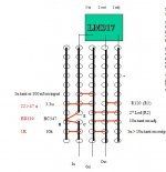
If it helps, this is how I build my 5v regs. 2*led are in series, combination of leds selected to give near 3.75v.
Red is for if you need more current (> 50ma)
Attachments
Last edited:
Do the Mundorf's have polarity or does it matter which leg goes where? Beginners question...I'll get those pictures to you this weekend Ray.
given the price...is there an equal alternative that is equally compact and somewhat cheaper?
No, they are film caps and they have no polarity. Also, it doesn't matter how you connect them. They have an outer-foil side, which should go to GND or the low-impedance side of the circuit. But the signal is so large that you won't notice the difference.
The EVO's are the lower cost alternative. Just compare their price to the Supreme Silver/Gold/Oil
My Super-Raygulator lives! I've turned the LED round and now get 4.82V out - is this sufficient for the DAC and other 5V circuits? I know why its a bit under - I was expecting the IN4148 to drop 0.7V but having read the datasheet it actually drops 1.0V. I can easily get some different LED's if needed.
and now get 4.82V out - is this sufficient for the DAC and other 5V circuits? I know why its a bit under - I was expecting the IN4148 to drop 0.7V but having read the datasheet it actually drops 1.0V. I can easily get some different LED's if needed.This Question is half offtopic. I want to add the Flea Clock to my 67. I allready have a Custom Transformer (build by the specs mentioned in the early pages) for an additional external clock. So it hast 9,5V AC secondary - the flea needs according to your site 12V. could be a bit tight after 9,5V AC rectifing. So my question: Should I driver the AD797 with lower voltage like 10V or would you recommend to use a voltage multiplier like the Delon Circuit before the volt. reg ?
thx in advance
thx in advance
A 9,5VAC winding won't be enough, the Flea needs 18VDC!
I don't know where you found that The Flea needs 12V, but I do use an assembled 12V supply-module for the Flea (the module from Conrad), maybe that is what you read somewhere? But it is first heavily modified.
It has a small 15V transformer on-board, which delivers a much higher voltage with a load as small as the Flea. So after replacing the 7812 with an 7818, this gives 18VDC output voltage. The rectifier cap is enlarged to 1000uF, this also helps to generate a larger secondary voltage. This way, it can be done with a 15VAC transformer, but it is just enough.
Lowering the supply of the AD797 is not recommended.
Oh sorry I was wrong. Yes it needs 18vdc. Somehow I must have misstaken the schematics of the flea it self. there is a 7812.
Mh I saw that you are using a modified Conrad module.
My intention was to use 9,5VAC winding from the custom transformer. I thought maybe there is a way to use a voltage multiplier. with around 18VAC -> lm317 (set to 14-15VDC) -> Flea 7812(replacing with lm317 or lt1805 adjust to 10VDC)...but this would be a heavy modification
My Super-Raygulator lives! I've turned the LED round
...
I can easily get some different LED's if needed.
Easier fix, reduce the value of the resistor feeding the LEDs - drop it to something like 220ohms or even 100, to push more current through the LEDs. The voltage will rise because the LED dynamic reistance is not zero but a very few tens of ohms (reducing slightly as you pour more curent through them.)
But to answer your question - yes 4.8x volts is enough for '5v' elements. 5v logic levels require a +/-5% tolerance, so 4.75-5.25v is all ok.
- Home
- Source & Line
- Digital Source
- Marantz CD63 & CD67 mods list