Just look at Fidelity Audio's CD63 upgrade page and found the following text which puzzles me:
"0 ohm metal film resistors (analogue psu)"
Why insert some 0 ohm metal film resistors to the psu ? I don't have a clue and may be someone can shed some lights on it. Is it the same using bare wires and where are the locations of these 0 ohm resistors?
"0 ohm metal film resistors (analogue psu)"
Why insert some 0 ohm metal film resistors to the psu ? I don't have a clue and may be someone can shed some lights on it. Is it the same using bare wires and where are the locations of these 0 ohm resistors?
Just look at Fidelity Audio's CD63 upgrade page and found the following text which puzzles me:
"0 ohm metal film resistors (analogue psu)"
Why insert some 0 ohm metal film resistors to the psu ? I don't have a clue and may be someone can shed some lights on it. Is it the same using bare wires and where are the locations of these 0 ohm resistors?
I was confused when I first saw 0 ohm resistors mentioned somewhere, after just reading the wikipedia entry I have been a little enlightened.
I was confused when I first saw 0 ohm resistors mentioned somewhere, after just reading the wikipedia entry I have been a little enlightened.
Yes I know 0 ohm resistors are used in Surface Mount PC boards BUT in modding CD63 I cannot see why 0 ohm resistor is used. A bare wire can do the job better here.
Hi Ray I have been looking at the list of mods for the Marantz CD63mkII-KI, great job by the way, I am looking to start doing a few mods, could you please advise where should i start for the greatest gains?
Thanks
Matt
Hi Matt,
Ray produced an excellent list of mods for the CD63 all those years ago. However, things have moved on a pace since then, although many of Ray's original ideas still apply. To have a major impact on sound quality in the early stages I would start by buying 3 toroidal transformers to replace the existing 1 tx. Look at Higlander's post 20311 for how to do this. You will then have the foundations in place to make the most of what you do after this... replace caps, voltage regs, clocks, HDAM bypass, DOS, etc.
Good luck. I knew nothing when I first came on here, and I now have a 3-box player which sounds like a high-end machine. I have learned a lot but I still have so much more to learn... and to do.
Hi Ray I have been looking at the list of mods for the Marantz CD63mkII-KI, great job by the way, I am looking to start doing a few mods, could you please advise where should i start for the greatest gains?
Thanks
Matt
You may wish to look at what I have done by blowing up the pictures that I have posted in the previous page:
http://www.diyaudio.com/forums/digi...ntz-cd63-cd67-mods-list-2034.html#post3947214
As a start change the opamps, remove the HDAM circuit and change the caps to better quality ones with bigger values. Use an independent external clock and deploy low noise voltage regulators. Of course the biggest gain is to change the stock Tx by 3 toroidal TXs.
Happy modding
")
Last edited:
Please refer to my post in #20311 on how to replace the stock TX with 3 toroidal TXs:
http://www.diyaudio.com/forums/digi...ntz-cd63-cd67-mods-list-2032.html#post3916418
Just now I have found out that there is a BIG typo in the wiring circuit diagram. The two TXs should be swapped (i.e. the 30VA 2X15V should be 50VA 2X12V instead) otherwise you will get too high a voltage for the servo circuitry !! It might blow out the three controller opamps for the servo.
On a separate issue from my experience I found the 47 ohm resistor generates too much heat and I have just ordered an electronics resistor like this:
http://cpc.farnell.com/bi-technolog...I+TECHNOLOGIES/TT+ELECTRONICS+-+RESISTOR,+47R
I hope it will generate less heat inside the casing. I will post the result when I have completed the mod.
Last edited:
You may retain the stock toroidal Tx for the analogue and the display panel. Add one 50VA 2X12V toroidal TX to supply the servo. You can order this TX from RS. Go to RS and search for it.Thanks for the replies, I have the KI version with the toroidal TX, would it still be necessary to change to a 3 TX psu, and if so do you have the part numbers for the TX's, also what do you recommend I use for the op amps?
For the opamps I recommend to use LM4562HA or LME49720HA.
Found this TX MCFE050/12 - MULTICOMP - TRANSFORMER, 50VA, 2 X 12V | Farnell UK would it be suitable?
I see that the op amp is a metal can type does this perform better than the 8DIP version of the op amp? if so would solder direct to the board of put in a socket for it to fit in.
CAN type opamp performs better. You can solder it directly onto the PCB or alternatively solder it onto a 8 pin socket.
Found this TX MCFE050/12 - MULTICOMP - TRANSFORMER, 50VA, 2 X 12V | Farnell UK would it be suitable?
Yes it works fine but I would not recommend this if you want to install 3 TXs as the size is too big. Try to use a TX without the plastic cover where the size is smaller.
I use this
http://uk.farnell.com/multicomp/mcta050-12/transformer-50va-2-x-12v/dp/9530363
and this
http://uk.rs-online.com/web/p/products/2237894/
Last edited:
Hi Ray I have been looking at the list of mods for the Marantz CD63mkII-KI, great job by the way, I am looking to start doing a few mods, could you please advise where should i start for the greatest gains?
Thanks
Matt
Hi Matt,
The first things that are relatively simple to do that come to my mind are:
- swap opamps
- add a decent clock
- add chassis damping
- swap rectifier diodes for schottkys
- remove muting transistors
- remove output caps
This should open up the sound a bit and add some peace & quiet to the music
Regards,
Ray
Hi Ray
I've bought a 12v relay PCB as shown (similar to that used by Higlander) and I've looked at the suggestions on the mods page and your CD67 mods pdf regarding the relay. To be honest, I'm a all at sea with this aspect of the mod and wondered if you or other users could provide a bit of guidance. I've marked component swaps or where I think the wires should go but would you mind assisting me with the remaining terminals?
Is it a case of wiring to the correct terminal? I assume the onboard transistor switches the relay rather than recycling one of the muting transistors?
Picture and diagram of relay wiring
Help very much appreciated.
The terminals marked COM1 and COM2 go to GND. The terminals NC1 and NC2 go to the emitter of QN07 resp. QN08 after they have been removed. VCC is indeed where the 12V from QN02 goes, GND terminals speak for themselves. The input goes to the base of either QN07 or QN08. If all is well, the relay should switch and open the contacts when music is played.
Ray
Modding CD63
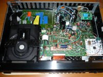
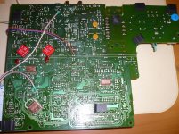
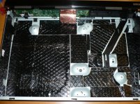
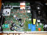
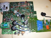
I have completed about 95% of the CD63 modding project for my friend and the only item left is to replace the stock TX with three toroidal TXs. I have uploaded a few photos here for reference.
I have tested the modded CD63 with the stock TX and everything works like a charm. With the 3 toroidal TXs put in there will be a boost in overall performance.
I am waiting for the TXs to arrive due to out of stock and hope I can complete the mod for my friend very soon.
Attachments
hi guys, ok so ive modded the player like ray suggested. think next step is rays output stage. anyway i decided too rebuild my chipamp and on testing i done a very stupid thing, i plugged the interconnects into the remote out part ( yes very silly off me ). now the remote has stopped working. ive check the remote switch its set to internal. so any ideas please?.
Hi,
Looks like some part of the remote circuit was damaged with that. Probably a transistor that needs replacement, my guess is QF51 or QF52. Use a generic NPN and PNP, that will work fine.
The other option is to disable the annoying remote switch completely. Have you ever flipped the switch accidentally while fumbling around with the interconnects? And then wondered if your remote was broken?
For the CD57/67 series:
Disable IR remote switch and RC-5 IN/OUT bus:
- Remove U125, U133 and DF52 to isolate the RC-5 signal.
- Remove RF52, RF54 and RF61 to disable the 5V power supply for this circuit.
- Insert a jumper wire from U125 (the hole farthest from QF61) to U133 (the hole near QF02).
hi ray,
yes i have flipped the switch in the past by accident. now ive tried to disable the switch by following the instructions above but the player wouldnt switch on. So i reversed as above to get it working. The player is the cd63, is it slightly different to the cd57/67 series?
yes i have flipped the switch in the past by accident. now ive tried to disable the switch by following the instructions above but the player wouldnt switch on. So i reversed as above to get it working. The player is the cd63, is it slightly different to the cd57/67 series?
- Home
- Source & Line
- Digital Source
- Marantz CD63 & CD67 mods list