rowemeister said:Here are some pics from my mod.
The reg pcb houses two circuits
1) 5V rail with 5V Audiocom Invisus with coils and 3 Blackgate 16V 100uF caps powering the DAC and Decoder
2) 12V rail with 12V superreg with coils and 2 Blackgate FK 16V 100uF caps powering Audiocom superclock II.
Both circuits are fed +20V from HexFED diodes.
I guess the decoder and the digital powersupply pen of the dac are still polluting the analog and clock powersupply of the dac?
 I would have done that differently (i actually did
 )
)mmm, hdam bypass, sounds so good. There's my evening gone, rediscovering anything I put on! Constantly blown away by the detail, clarity, precision and dynamics (something I didn't expect!), particularly in the bass! Listening to some old REM it often reminded me of what electric bass sounds like live on a powerful PA system. I've heard many noises and bits of distortion and hiss I'm sure I haven't ever heard before.
SimontY said:mmm, hdam bypass, sounds so good.
Now you understand the power of the marketing.
This Hdam are publicized by Marantz and the "guru" Ken Ishiwata , as the 8 World Wonder...
")
Tube_Dude said:
Now you understand the power of the marketing.
This Hdam are publicized by Marantz and the "guru" Ken Ishiwata , as the 8 World Wonder...
Yeh, it's ridiculous really! That it can sound so much better when you disable the circuit, that's *supposed* to set it apart, is just madness!
Or maybe we've all done other mods at the same time and are hearing cumulative benefits.
Guido said:
I have actually designed the regs pcb so that I can later fit a TX if need be.
The regs used should be nearly zero noise (according to Audiocom).
I have 5 super low noise regulator pcbs fitted to this cdp and surley the noise on any line will now be minimal!
I guess the decoder and the digital powersupply pen of the dac are still polluting the analog and clock powersupply of the dac? I would have done that differently (i actually did )
I have actually designed the regs pcb so that I can later fit a TX if need be.
The regs used should be nearly zero noise (according to Audiocom).
I have 5 super low noise regulator pcbs fitted to this cdp and surley the noise on any line will now be minimal!
guido said:
I guess the decoder and the digital powersupply pen of the dac are still polluting the analog and clock powersupply of the dac?
rowemeister said:
I have actually designed the regs pcb so that I can later fit a TX if need be.
The regs used should be nearly zero noise (according to Audiocom).
I have 5 super low noise regulator pcbs fitted to this cdp and surley the noise on any line will now be minimal!
Hi rowemeister!
Some mod eh? I think you will like the OPA627 + OPA132 even better. Make sure you put the 627 after the DAC and 132 in the filter.
What Guido means is that the regs are o.k. obviously, but the noise is not coming from them, it's coming out of the DAC!
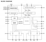
Take a look at the datasheet. The SM5872 has separate +5V lines for the digital part (pins 15 & 16), the analog part (pins 17, 19, 21, 22, 24, 26) and the clock part (pins 2 & 27). Since the supply lines of the DAC are not separated completely now, some (digital...) noise will be coupled to other (analog...) stages. If you tie the clock part to the supply of your external clock and the digital part to the +5V you use for the decoder, you can fit a third (clean) +5V for the analog part. Have I 'translated' this correctly Guido?
The key is to separate these lines. You can do that by looking at the board layout.
The clock part is just two internal gates that used to form the oscillator, but they still carry the 16,9MHz. It's easy: it is already separated, it get's +5V through RD01. You should tie it to the external clock supply to keep all the noise in one place.
The digital AND the analog part get +5V through U164. Then through RD04 to the digital part, and U200 to the analog part. If you take these two out, you have separated these parts too

Ray.
Attachments
rowemeister said:Now then.. with out the service manual infront of me, are the decoders 2 5V inputs the same or is one analogue and one digital?
Greetings fellow tweaker!
Well, I guess for the decoder you can say the same as for the DAC. The SAA7345 has three different 5V connections actually. One for the analog front-end, where the analog HF signal enters the chip, and two for digital internal logic and I/O buffers. All this wisdom came out of the datasheet of course.
I already experimented a bit with this, and placed an RC filter (1mH + 220u low-ESR) in each powerline, but the chip didn't seem to like it. I think it has to do with internal reference voltages or something like that. The chip doesn't like too high impedances between the different power lines. There's a note also about this in the datasheet.
In the CD67 (which uses a similar SAA7372) they separated the 5V lines a bit by using two RC feeds for the analog and digital part and by inserting ferrite inductors in the digital lines.
Ray.
SimontY said:
Good evening,
Kiwame eh? Sounds fancy
I remember not liking the change in some ways when I replaced lots of the carbon ones in the output stage of the cd63 with cheap 1% 1/4w metal films. I felt the sound lost some charm or something. It's something I've been meaning to investigate.
The only series resistance in my x-overs is a little piece of resistance wire to bring the tweets down a fraction
Hi Simon,
They sound fancy indeed, and they're not too pricy I think. And they do come in 5W, so I first used them in my tube-amp and tried them in the cross-over later on. It had a 2,2R cement wire-wound to bring the tweeter down, but this sounds a lot better. I tried MOX also, but I didn't like them, sounded like an electric saw.
For the filter in the players I used 0,1% Welwyn RC55Y in my CD67, and 0,1% BC MMA0204 smd resistors in my CD57 so far. Both changes made a big improvement, but I still have to do a critical comparison between the two, with the same opamps in there, to see which one I like best.
Changing these to any 0,1% brings a lot of detail to the sound, almost as much change as the removal of the HDAM
But don't forget to do the filter caps also.
Ray.
rowemeister said:I have 16V 470uF blackgates on C510/C511 to the decoder
And a Silmic on the HF 5V (C504)
The two digital supplies are on the same line with one source voltage coming in.
Hi rowemeister,
So you have a separate regulator that supplies C510 (analog), and the digital C511 & 513 are connected to a second reg?
When I look at my board, C513 is connected directly to the 5V line, and C509/510 through R511. In the schematic however, C513 is connected to C511/512 and then though R508 to the 5V line. The schematic and board in the manual are different (again...)
Ray.
I have seperated rails now yes. I just need to build a reg for the clock voltage i/p of the DAC.
I have just looked @ another KI pcb I have here at work and C513 is connected direct to the 5V rail.
So when I thought I had pin 15 running from my regs I was wrong!!!
I will have to change this
My PM66 KI has loads of errors on the sch.
Nice one marantz!!!!
I have just looked @ another KI pcb I have here at work and C513 is connected direct to the 5V rail.
So when I thought I had pin 15 running from my regs I was wrong!!!
I will have to change this
My PM66 KI has loads of errors on the sch.
Nice one marantz!!!!
6h5c said:
Hi Simon,
They sound fancy indeed, and they're not too pricy I think. And they do come in 5W, so I first used them in my tube-amp and tried them in the cross-over later on. It had a 2,2R cement wire-wound to bring the tweeter down, but this sounds a lot better. I tried MOX also, but I didn't like them, sounded like an electric saw.
For the filter in the players I used 0,1% Welwyn RC55Y in my CD67, and 0,1% BC MMA0204 smd resistors in my CD57 so far. Both changes made a big improvement, but I still have to do a critical comparison between the two, with the same opamps in there, to see which one I like best.
Changing these to any 0,1% brings a lot of detail to the sound, almost as much change as the removal of the HDAM
But don't forget to do the filter caps also.
Ray.
Hi Ray
Interesting to hear about those resistors... I did compare white coffins to MOX and found the MOX to be a slight improvement, but I felt they still put plenty of grain (electric saw?
 ) into the treble. But when I altered my x-overs I found I didn't need much padding at all so all I use is about 15cm of resistance wire, which has no real character to it I find.
I changed the resistors in the 63's output area to better than 1% metal film, and the sound got better and worse. I really can't agree with you when you say "using 0.1% brings a lot of detail", because my experience was more slight than that. Perhaps you used nicer resistors than me. Please don't think I question your judgement - I simply had a less positive experience in my system with 2 pence resistors.
I would say, particularly to anyone considering modding their CD63SE/KI that the following mods made extremely important changes to the sound quality that make it produce great music:
1 - removal of dc blocking caps* (and muting transistors)
2 - add on clock with totally dedicated psu
3 - op-amps to opa627 or other top notch solution
4 - damping chassis (not too much tho!!) and using 3 wooden cones as feet
5 - bypassing hdam
*if your amp can deal with the possible dc, but just do it, come on!
And that's more or less the order they should be done, but it seems obvious to upgrade the psu too. All I have done (other than separate clock psu) is to beef up some caps, install schottky diodes, and replace 'fuse resistors' with ~1R inductors. And obviosuly some X rated mains filter caps, and a CAT5 braided power cable. And it runs off a 500va iso. trafo.
I have not changed my filter caps around the op-amps yet, apart from two, which according to the TNT guide make the treble rolloff earlier. These are silvered mica.
rowemeister said:I have seperated rails now yes. I just need to build a reg for the clock voltage i/p of the DAC.
I have just looked @ another KI pcb I have here at work and C513 is connected direct to the 5V rail.
So when I thought I had pin 15 running from my regs I was wrong!!!
So if you separate digital and analog this way, it seems works fine. I think i'm going to look into this again and give it a try.
Can you tell me when things are still stable, if you have changed the C513 supply?
Ray.
Hi Simon,
That's strange
Maybe you had rusty resistors
You should try again with some different types then, it really is worth it.
And while you're at it, change the filter caps to 1% (silver-mica, MKP or styroflex), especially the ones right after the DAC. This part is supposed to be as symmetric as possible due to the differential outputs.
I know the TNT mod where they change the 120p cap in the analog filter, to get rid of the slight bump in the high region. But this is not the right way to do it!
Take a look at Pedja's page: http://users.verat.net/~pedjarogic/audio/cd_mods/cd_mods.htm
The idea is to lower C605/606. I use 560pF now. You can get rid of L601/602 too, they don't use it in the CD67 anymore.
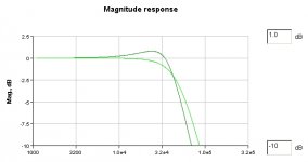
If you want to simulate the filter you can use this handy tool from Analog Devices. In the diagram it will show a nice before and after graph if you fiddle around with the values a bit.
Ray.
That's strange
Maybe you had rusty resistors
You should try again with some different types then, it really is worth it.
And while you're at it, change the filter caps to 1% (silver-mica, MKP or styroflex), especially the ones right after the DAC. This part is supposed to be as symmetric as possible due to the differential outputs.
I know the TNT mod where they change the 120p cap in the analog filter, to get rid of the slight bump in the high region. But this is not the right way to do it!
Take a look at Pedja's page: http://users.verat.net/~pedjarogic/audio/cd_mods/cd_mods.htm
The idea is to lower C605/606. I use 560pF now. You can get rid of L601/602 too, they don't use it in the CD67 anymore.
If you want to simulate the filter you can use this handy tool from Analog Devices. In the diagram it will show a nice before and after graph if you fiddle around with the values a bit.
Ray.
rowemeister said:I have all silver mica after DAC
So what you are saying is ditch the inductors and change the value of the caps to 560pF.
Yep. Well, actually it's what Pedja is saying, just passin' the word

You can play around with the value and see how the curve changes. Here's a pic of the 'before' (1nF) and 'after' (560p) amplitude curve as it comes out of the Analog Devices tool.
It's a simple mod, i'm curious what you think of the sound.
Ray.
Attachments
- Home
- Source & Line
- Digital Source
- Marantz CD63 & CD67 mods list