Hello people,
Is anybody have expirience to put pcm63p-k in parralel mode?
Today I've done it with my Rotel 991 .Little bit about previous mods:
1.Switched pcm63 na pcm 63 pk (better bass)
2.Switched opa2132 to opa627 (overall high sound improvement)
So today I've done 3rd step,put pcm63 in parralel piggy-back mode..Result is strange.
Good sites:
1.Overall excellent resolution.
2.Excellent deep bass (in my threephonic I put sub now to -4 db,so high is level of bass right now)
3.Very analog voices ,violine and percussions.
Bad sites:
1.Highs get like lower .
2.On fast music like heavy metal I feel like some loose of dynamic.
When I hear something like Norah Jones or Diana Krall,and especially violine, it plays like HIGH-END sacd player,but heavy metal start to be very boring.
For me will be very interesting if anybody have also delas with pcm63-pk in piggy back configuration.May be master clock can be solution?
No more stack no more
Hi,
today I stacked 2 x 4 PCM56, leaving internal op amps and I/V resistors of the three upper chips disconnected.
They were plugged into sockets in a Kenwood player.
I measured with the spectrum analyzer as always, and there has been zero improvement compared to any of the single chips.
I did that before with pairs of TDA1541 and there seemed to be an improvement most of times.
Sometimes two harmonics together behave better and sometimes worse, compared to each single chip.
For example -60 & -58 gives -59 most of time, but also could give -57 or -61.
Statistically the average of second to 9th harmonics of any single chip and the 4-chip-stack was -60 dB +/-1 dB.
Also noise did not improve.
Two chips could be matched to improve all harmonics but it is very difficult with 3 or 4 or 5 or...
Or maybe BB and Philips behave different...
Anyway if you have two chips, one with bad K3 and another with bad K4, you can mix them together and get acceptable K3 and K4 but the sum will be the same.
fumihiko said:Dr.H san KONNICHIWA
don't connect p1,3,4,9,10,23,24,25 each PCM63
Please make a Capaciter separate each PCM63
if parraleling up there pins
can't take better result.
Have you tried it?
AnthonyAsh san KONNICHIWA
I tried paralleling up PCM63
at first, piggy back mode
but, It was a result worse than single use.
I asked BB japan
answer, operating point is mutually different, please do not common connection of the capacitor.
tried again,not common connection of the capacitor.
I take good result
better method is making independent I/V stage parallel.
Have you tried it?
I tried paralleling up PCM63
at first, piggy back mode
but, It was a result worse than single use.
I asked BB japan
answer, operating point is mutually different, please do not common connection of the capacitor.
tried again,not common connection of the capacitor.
I take good result
better method is making independent I/V stage parallel.
Thánk you for info. on which pin I need to put capacitor?fumihiko said:AnthonyAsh san KONNICHIWA
I tried paralleling up PCM63
at first, piggy back mode
but, It was a result worse than single use.
I asked BB japan
answer, operating point is mutually different, please do not common connection of the capacitor.
tried again,not common connection of the capacitor.
I take good result
better method is making independent I/V stage parallel.
Fumihiko san, Konnichiwa
Thanks for the interesting response! I am not sure which capacitor you refer to.
Pin 1 is the servo decouple
Pin 3 is the reference decouple
Pin 4 is the Offset decouple
Pin 9 is the Rfeedback pin
Pin 10 is connected to pin 9
Pin 23 is the "Upper B2 ADJ" pin
Pin 24 is the "lower B2 ADJ" pin
Pin 25 is "potentiometer voltage" pin
Of these pins, 23, 24, 1, 3 and 4 are decoupled to ground through caps, so I would assume you are refering to these capacitors?
What do you do with pin 9 and 10 which appear to be used by the analog outputs stage op-amps? Do you connect them to your IV stage? If so they are effectively in parallel with the existing DAC.
Thanks for your input, domoarrigoto
Ryan
Dr.H san KONNICHIWA
upper chips capacitors and lower chip capacitors must be independent.
upper chips resistor-network and lower chips resistor-network must be independent.
can connect upper and lower
digital-input , power-supply and signal-out only")
4paralleling PCM63PK and multiple(independent) IV satage
but now,8paralleling piggy-backing PCM63PK and common IV stage
my DAC too small , can't have multiple IV stage
Of these pins, 23, 24, 1, 3 and 4 are decoupled to ground through caps, so I would assume you are refering to these capacitors?
upper chips capacitors and lower chip capacitors must be independent.
upper chips resistor-network and lower chips resistor-network must be independent.
can connect upper and lower
digital-input , power-supply and signal-out only
1st revWhat do you do with pin 9 and 10 which appear to be used by the analog outputs stage op-amps? Do you connect them to your IV stage? If so they are effectively in parallel with the existing DAC.
4paralleling PCM63PK and multiple(independent) IV satage
but now,8paralleling piggy-backing PCM63PK and common IV stage
my DAC too small , can't have multiple IV stage
Attachments
Dr.H said:Fumihiko san, Konnichiwa
Thanks for the interesting response! I am not sure which capacitor you refer to.
Pin 1 is the servo decouple
Pin 3 is the reference decouple
Pin 4 is the Offset decouple
Pin 9 is the Rfeedback pin
Pin 10 is connected to pin 9
Pin 23 is the "Upper B2 ADJ" pin
Pin 24 is the "lower B2 ADJ" pin
Pin 25 is "potentiometer voltage" pin
Of these pins, 23, 24, 1, 3 and 4 are decoupled to ground through caps, so I would assume you are refering to these capacitors?
What do you do with pin 9 and 10 which appear to be used by the analog outputs stage op-amps? Do you connect them to your IV stage? If so they are effectively in parallel with the existing DAC.
Thanks for your input, domoarrigoto
Ryan
Dear Mr.Fumihiko san, Konnichiwa
Do you have a diagramm?
Sincerely,A
fumihiko said:
Not datasheet,but schematics of how you connected 2 pcm63 toghether.
AnthonyAsh said:
Not datasheet,but schematics of how you connected 2 pcm63 toghether.
It is easy, parallel means connect Iout together.
And digital lines.
And grounds.
And supply rails. Or give one extra supply each chip.
But not individual (decoupling) pins.
This is why TDA1541 can not be stacked. Lots of individual decoupling pins. All must be placed on the pcb.
TDA1543 can be stacked. Very simple "tcheap".
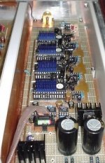
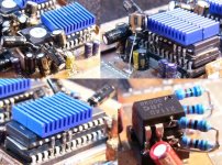
AnthonyAsh san KONNICHIWA
my piggy back PCM63 and NJM2114
Not datasheet,but schematics of how you connected 2 pcm63 toghether.
my piggy back PCM63 and NJM2114
Attachments
Fumihiko san Konnichiwa
Thanks for the pictures. Just a couple of questions:
1. Did you connect Pin 5 of the upper and lower chips together, i.e. are they in parallel like pin 18?
2. Did you connect Pin 1 to the -V supply via its own independant capacitor?
Finally, vs the single chip, what are the sonic benefits of going with the parallel setup?
Thanks
Ryan
Dear Dr.H san
pin1 to -V supply via own independent capacitor.
pin3 and 4, via own independent capacitor
pin5,6,7,11,12,13,18,20,21,28 connected upper and lower.1. Did you connect Pin 5 of the upper and lower chips together, i.e. are they in parallel like pin 18?
pin1 to -V supply via own independent capacitor.
pin3 and 4, via own independent capacitor
Dr.H said:Fumihiko san,
Thanks! What would you describe as the benefits of using the parallel chips vs just using one chip?
I will try the mod sometime in the near future and post my results here. Thanks for your input!
Ryan
Dear Mr. Fumihiko,
For me is also very interesting what you gain when you used your pcm63 config?
Dear
what a difference ,single DAC and multiple DAC?
single use , it is thin sound
dual , what a different?
triple , good sound!
quad , I was surprised
8 paralelled , had been moved!
I heard and compared, accuphase DC-91
just a little difference.
I think,best solution is 4 to 8 paralleled DAC
actually, accuphase paralleled 4 to 8.
now I try 4 paralled CS4334
- Status
- This old topic is closed. If you want to reopen this topic, contact a moderator using the "Report Post" button.
- Home
- Source & Line
- Digital Source
- pcm63pk in piggy back mode.