Finally, after working on my audio DAC for years and years, I have an up-and-running prototype with all parts owned by myself, nothing borrowed from the various labs where I have worked.
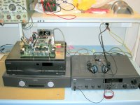
Just wanted to show you some pictures of it!
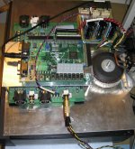
Some details:
- I tap the CD player I2S signal and the crystal oscillator there. S/PDIF is an option. (Want to improve oscillator in CD player and move it to the DAC board.)
- Home-made 8x digital oversampling filter implemented in Xilinx FPGA. (Want to experiment more with digital filters.)
- Home-made analog filter built around on BB opa2132 (a newer 2134 with lower input offset voltage error).
- Three different filter / DAC combinations. Possible to compare pcm1794 and pcm1794 with same digital and analog filter.
I hope I get to make the top lid for it and bring it home tonight.
Greetings,
Børge
Just wanted to show you some pictures of it!
Some details:
- I tap the CD player I2S signal and the crystal oscillator there. S/PDIF is an option. (Want to improve oscillator in CD player and move it to the DAC board.)
- Home-made 8x digital oversampling filter implemented in Xilinx FPGA. (Want to experiment more with digital filters.)
- Home-made analog filter built around on BB opa2132 (a newer 2134 with lower input offset voltage error).
- Three different filter / DAC combinations. Possible to compare pcm1794 and pcm1794 with same digital and analog filter.
I hope I get to make the top lid for it and bring it home tonight.
Greetings,
Børge
Attachments
Originally posted by borges
Home-made 8x digital oversampling filter implemented in Xilinx FPGA. (Want to experiment more with digital filters.)
How many CLB's does the filter use ?
Re: Re: DAC finally assembled
The 102400 byte limit in attachment size limits the kind of pictures I can attach. The power supply I etched myself. The Xilinx board I got straight from Xilinx, and the DAC board was made in Norway by Elprint. They are quite nice with a matrix where you can choose quantities and production times to find a fairly good price. I tried making it in my tank, but it got too big. Besides, no through-hole plating made it a little hard to interface the PCM1794 DACs.
The current filter is for a Spartan 3/200. I have also made it for a Spartan 2e/300 with larger filters. I have been using distributed arithmetic filters this far, but I believe I can make longer filters with the S3 embedded multipliers.
What the code now contains is this: I2S reader, PCM1704 writer, 2-channel FIR doing 2x oversampling, 2-channel FIR doing a final 4x oversampling.
The first filter has 157 taps (every second tap is zero), the second filter has 154 taps (no symmetry/zeros exploit). Both filters use 21-bit coefficient data. Output from first and second filters are truncated to 24 bits. It was actually better to use single rate FIRs and manually insert zeros for oversampling, than to use actual oversampling filters. The reason is that oversamplers can only be single channel devices in Xilinx's Core Generator. The glue logic got a little tricky, though.
Just finished a rerun of the FPGA compilation. Here's what it says:
Design Summary:
Number of errors: 0
Number of warnings: 0
Logic Utilization:
Number of Slice Flip Flops: 2,676 out of 3,840 69%
Number of 4 input LUTs: 1,867 out of 3,840 48%
Logic Distribution:
Number of occupied Slices: 1,797 out of 1,920 93%
Number of Slices containing only related logic: 1,797 out of 1,797 100%
Number of Slices containing unrelated logic: 0 out of 1,797 0%
*See NOTES below for an explanation of the effects of unrelated logic
Total Number 4 input LUTs: 2,906 out of 3,840 75%
Number used as logic: 1,867
Number used as a route-thru: 85
Number used as Shift registers: 954
Number of bonded IOBs: 25 out of 173 14%
IOB Flip Flops: 9
Number of GCLKs: 1 out of 8 12%
Number of DCMs: 1 out of 4 25%
Total equivalent gate count for design: 106,270
Additional JTAG gate count for IOBs: 1,200
Greetings,
Børge
ZERS said:Hi,
closer pics soon availables ?
Anyway, which company did manufacture your PCB ?
Regards
The 102400 byte limit in attachment size limits the kind of pictures I can attach. The power supply I etched myself. The Xilinx board I got straight from Xilinx, and the DAC board was made in Norway by Elprint. They are quite nice with a matrix where you can choose quantities and production times to find a fairly good price. I tried making it in my tank, but it got too big. Besides, no through-hole plating made it a little hard to interface the PCM1794 DACs.
rfbrw said:
How many CLB's does the filter use ?
The current filter is for a Spartan 3/200. I have also made it for a Spartan 2e/300 with larger filters. I have been using distributed arithmetic filters this far, but I believe I can make longer filters with the S3 embedded multipliers.
What the code now contains is this: I2S reader, PCM1704 writer, 2-channel FIR doing 2x oversampling, 2-channel FIR doing a final 4x oversampling.
The first filter has 157 taps (every second tap is zero), the second filter has 154 taps (no symmetry/zeros exploit). Both filters use 21-bit coefficient data. Output from first and second filters are truncated to 24 bits. It was actually better to use single rate FIRs and manually insert zeros for oversampling, than to use actual oversampling filters. The reason is that oversamplers can only be single channel devices in Xilinx's Core Generator. The glue logic got a little tricky, though.
Just finished a rerun of the FPGA compilation. Here's what it says:
Design Summary:
Number of errors: 0
Number of warnings: 0
Logic Utilization:
Number of Slice Flip Flops: 2,676 out of 3,840 69%
Number of 4 input LUTs: 1,867 out of 3,840 48%
Logic Distribution:
Number of occupied Slices: 1,797 out of 1,920 93%
Number of Slices containing only related logic: 1,797 out of 1,797 100%
Number of Slices containing unrelated logic: 0 out of 1,797 0%
*See NOTES below for an explanation of the effects of unrelated logic
Total Number 4 input LUTs: 2,906 out of 3,840 75%
Number used as logic: 1,867
Number used as a route-thru: 85
Number used as Shift registers: 954
Number of bonded IOBs: 25 out of 173 14%
IOB Flip Flops: 9
Number of GCLKs: 1 out of 8 12%
Number of DCMs: 1 out of 4 25%
Total equivalent gate count for design: 106,270
Additional JTAG gate count for IOBs: 1,200
Greetings,
Børge
Hi Lgrau,
that's my plan indeed! Between fixing up my appartment and changing jobs I plan to implement downloadable filter coefficients. Then I can be in a listening position with my PC around and dump out fresh coefficients from Octave or Matlab.
For that to work I have to write Verilog code that implements an oversampler with Xilinx MACs. (You don't happen to have any such code lying around, do you? Right now I have a Verilog template written in Matlab.) I plan to store separate coefficients for L and R. Might sound like overkill, but that way I can use one of these sets as active Xover for one channel.
This stuff only gets really cool when I start using the FPGA filter to compensate for loudspeaker phase / dB response in addition to Xover. I mean there are 24 bit DACs lying around, so there should be some overhead to correct for "errors" further down the signal chain. What do you think?
Greetings,
Børge
Re: Analog Filter
Do you have a schematic showing what you mean?
The I/V conversion I use today is pretty straight forward with inverting opamps. For the PCM1794 I also have an experimental setup with passive combined I/V and filtering. Trouble with that chip is that it pumps out 6.2mA of DC current that I don't want to let offset my output voltage.
As I recall it, the PCM1794 likes to send its single-ended output curent into a 0V potential. The inverting input of an opamp (whos non-inverting input is at ground) gets you pretty close to that. The 6.2mA I remove from the inverting input by means of a TL431 based current sink. There's one sink for each PCM1794 output pin. I wanted full DC response, so there's no servoing. This means outputs are the closest to 0mV after 30 minutes of operation in room temperature")
I use the DAC to evaluate two different analog filters, so I'm not using the datasheet's completely-differential-all-the-way schematic. Rater, I use two single-ended setups for the opamp-based filter.
The other (passive) filter is differential with non-inverting single-ended gain/buffer opamps on its outputs. There is a PMOS common-gate transistor gated at ground to place the PCM1794 output pin approximately at 0.7V. I know this is not ideal, but board space and development time was very limited at that stage.
So Patrick, any suggestions as to building a nice I/V converter with fixed - and linear - output resistance and possibly some sort of servo that gets the DC current, let's have it! I'd like to improve the filter/DAC interface with current sink and all. Right now I must bias the filter at some unwanted voltages because the bipolar current I get (after sinking the 6.2mA) must go to a voltage which is always below 0V (due to the CG PMOS). I'd like to have a bipolar current that I can put into a 0V potential without introducing too much noise and at the same time keeping the DAC chip happy.
Greetings,
Børge
EUVL said:Any plans for a discrete JFET analog filter ?
Such effort !! I wish I had the stemina.
Patrick
Do you have a schematic showing what you mean?
The I/V conversion I use today is pretty straight forward with inverting opamps. For the PCM1794 I also have an experimental setup with passive combined I/V and filtering. Trouble with that chip is that it pumps out 6.2mA of DC current that I don't want to let offset my output voltage.
As I recall it, the PCM1794 likes to send its single-ended output curent into a 0V potential. The inverting input of an opamp (whos non-inverting input is at ground) gets you pretty close to that. The 6.2mA I remove from the inverting input by means of a TL431 based current sink. There's one sink for each PCM1794 output pin. I wanted full DC response, so there's no servoing. This means outputs are the closest to 0mV after 30 minutes of operation in room temperature
I use the DAC to evaluate two different analog filters, so I'm not using the datasheet's completely-differential-all-the-way schematic. Rater, I use two single-ended setups for the opamp-based filter.
The other (passive) filter is differential with non-inverting single-ended gain/buffer opamps on its outputs. There is a PMOS common-gate transistor gated at ground to place the PCM1794 output pin approximately at 0.7V. I know this is not ideal, but board space and development time was very limited at that stage.
So Patrick, any suggestions as to building a nice I/V converter with fixed - and linear - output resistance and possibly some sort of servo that gets the DC current, let's have it! I'd like to improve the filter/DAC interface with current sink and all. Right now I must bias the filter at some unwanted voltages because the bipolar current I get (after sinking the 6.2mA) must go to a voltage which is always below 0V (due to the CG PMOS). I'd like to have a bipolar current that I can put into a 0V potential without introducing too much noise and at the same time keeping the DAC chip happy.
Greetings,
Børge
Discrete Opamps
There are plenty of choices on the internet.
Borbely has circuits on his site (www.borbelyaudio.com) for I/V conversion as well as JFET buffers.
If you want to use passive I/V through a resistor, and only need unity gain, then Richard Perez (justcallmedad) has posted a very simple circuit a while ago on this Digital Forum. I think the title is Sony SCD mod or something like that.
You probably know much much more electronics than I do, so I don't think you need any advice even if you need to adapt one of those circuits.
(And yes, I am building Richard's circuit to modify my Sony, but do not have the guts / time yet to fiddle with the digital stuff. I just thought what a waste to use OPA2132 for analog after all the hard work, even if you bias them to class A. But others might have different opinions of course.)
Patrick
I agree I should perhaps use different opamps. But the board that I have right now is for filter and DAC coparison. There just wasn't the space (nor budget) to go all out on all those opamps or all-fancy on the biasing and power. Some time soon (I hope) I'll know which filter to gamble on. Then I'll dive into the analog aspects of it. And I'll improve the oscillator. And I'll replace the LM317/337 regulators. Wish I didn't need a daytime job, I'd be soldering all day.
Do you know how to bias the 2132 in class A? I have usually just plugged the opamps right in. This is a dual-amp device, so there are no other pins available. (I use the chips differentially where possible. Nowhere does L and R audio signals go through the same opamp.)
Greetings,
Børge
Do you know how to bias the 2132 in class A? I have usually just plugged the opamps right in. This is a dual-amp device, so there are no other pins available. (I use the chips differentially where possible. Nowhere does L and R audio signals go through the same opamp.)
Greetings,
Børge
Opamp Bias
> Do you know how to bias the 2132 in class A?
Connect each of the outputs to the negative rail with a constant current diode (Either J5xx from Vishay or 1N53xx). Current depends on your load. I like the 1N53xx better as they come like a 0702 resistor instead of TO92. So you can solder them directly on the opamp legs (assuming you are using DIL and not SMD) without any change in PCB. If you don't like them, then just unsolder them, simple as that. I think you can also get them in SMD (CCLMxxx), but mods becomes tricky.
Simply trick, well known. I used it in my first DIY (opamp phono using AD797/OPA637, 2mA bias). Make a real difference.
> And I'll replace the LM317/337 regulators.
Try batteries. I am hooked on them.
Patrick
- Status
- This old topic is closed. If you want to reopen this topic, contact a moderator using the "Report Post" button.
- Home
- Source & Line
- Digital Source
- DAC finally assembled