Hi!
I ha ve just implemented a Kawk clock 7 on a home made PCB.
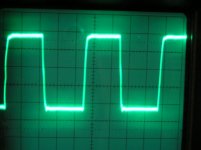
In my measures I experience a "big" undershoot and some "ringing" in the low cycle.
What is causing the undershoot?
Is this due to a design error from my side or is it supposed to do that?
If it is error, any idea where the error might ?
How about rise and fall times? i measure appr. 2 ns fall time and 6 ns rise time (22.5792MHz oscillator). Is this a trimming issue?
I will try to get some printout from my measure if it would help.
Thanx!
//Niklas
I ha ve just implemented a Kawk clock 7 on a home made PCB.
In my measures I experience a "big" undershoot and some "ringing" in the low cycle.
What is causing the undershoot?
Is this due to a design error from my side or is it supposed to do that?
If it is error, any idea where the error might ?
How about rise and fall times? i measure appr. 2 ns fall time and 6 ns rise time (22.5792MHz oscillator). Is this a trimming issue?
I will try to get some printout from my measure if it would help.
Thanx!
//Niklas
Hi Niklas, Don't worry too much. The ringing may be due to the measuring setup. Even the duty cycle adjustment is not critical as only the rising edge is used by then CDP.Niklas said:Hi!
I have just implemented a Kwak clock 7 on a home made PCB.
In my measures I experience a "big" undershoot and some "ringing" in the low cycle.
What is causing the undershoot?
Is this due to a design error from my side or is it supposed to do that?
If it is error, any idea where the error might ?
How about rise and fall times? I measure appr. 2 ns fall time and 6 ns rise time (22.5792MHz oscillator). Is this a trimming issue?
I will try to get some printout from my measure if it would help.
Thanx!
//Niklas

Re: Re: Undershoot in Kwak clock 7
Hi,
If it is due to the setup, you should see symmetrical ringing. Otherwise it is due to the circuit.
This does not implicate it is bad but I see it more often, for example due to asymetrical output impedance.
By the way, some converters convert at the falling edge. I've seen DACs where the jitter on the falling edge was significantly higher than on the rising edge......
best regards
-
Elso Kwak said:
Hi Niklas, Don't worry too much. The ringing may be due to the measuring setup. Even the duty cycle adjustment is not critical as only the rising edge is used by then CDP.
Hi,
If it is due to the setup, you should see symmetrical ringing. Otherwise it is due to the circuit.
This does not implicate it is bad but I see it more often, for example due to asymetrical output impedance.
By the way, some converters convert at the falling edge. I've seen DACs where the jitter on the falling edge was significantly higher than on the rising edge......
best regards
-
Now this is interesting. Which audio DAC is working on the falling edge of clock? Just curious. Most modern DACs have OSC inside synched with the external reference clock. It's odd that the internal OSC would synch with falling edges.
Anyway, rising edge, falling edge, the 2ns and 6ns setup time are perfectly fine as far as the timing jitter is under control.
Most XO stability tests are done through the rising edge of the signal so it's not a surprise to see worse jitter performance on the falling edges; the circuit inside XO is mostly not symmetric anyway. However, does this really matter?
lost email
Hello Finneybear,
Upon receipt of the boards I immediately wrote you an email to thank you. Apparently the email never did make it but the boards did. Thanks again!

finneybear said:BTW, Elso, have you ever received the conversion boards yet? I am wondering if they got lost somewhere across Atlantic.
Hello Finneybear,
Upon receipt of the boards I immediately wrote you an email to thank you. Apparently the email never did make it but the boards did. Thanks again!
Falling edge looking better....
Hi guys!
You say falling edge usually look worse than rising edge.
I must say my falling edge looks better then my rising in a jitter type of view. I must say i am pretty unexperienced with digital clock signal so maybe i am wrong.
Though, using my tektronix scope with Instavu, I get a more "spread out" rising edge, and a very thin falling edge. From that i draw the conclusion that the rising edge is more jittery (made up word maybe??).
As far as i know the sampling instant must vary much more for a slow rise time than for a very fast one.
I will try to get a print out to illustrate what i try to explain, a picture says more than 1000 words =).
//Niklas
finneybear said:Now this is interesting. Which audio DAC is working on the falling edge of clock? Just curious. Most modern DACs have OSC inside synched with the external reference clock. It's odd that the internal OSC would synch with falling edges.
Anyway, rising edge, falling edge, the 2ns and 6ns setup time are perfectly fine as far as the timing jitter is under control.
Most XO stability tests are done through the rising edge of the signal so it's not a surprise to see worse jitter performance on the falling edges; the circuit inside XO is mostly not symmetric anyway. However, does this really matter?
Hi
What do you mean with " the internal OSC" ?
I do not remember the DAC converting at falling edge, it was many years ago
Why would an XO have worse specs at falling edge ?
To end with, I measure my clocks at bothe edges. And yes, the duty cycle does not matter that much, it is the timing variation of th edge used for conversion....
cheers
Re: Re: Undershoot in Kwak clock 7
If a short 50 ohm coax cable is used to connect directly to the scope, and the 50 ohm resistor at the output IS present, no ringing can be seen. At least in my setup, AD8611 and AD8561 devices /the first one has higher SR/lower tranzition time/, double-layer PCB, 100nF+10nF decoupling next to the chip etc.
The circuit is great /and simple /
Regards
YES, I experience similar ringing differences, but they are due to the scope probe /the ringings/ and due to different slew rate /the difference between rise/fall/Elso Kwak said:
Hi Niklas, Don't worry too much. The ringing may be due to the measuring setup. Even the duty cycle adjustment is not critical as only the rising edge is used by then CDP.
If a short 50 ohm coax cable is used to connect directly to the scope, and the 50 ohm resistor at the output IS present, no ringing can be seen. At least in my setup, AD8611 and AD8561 devices /the first one has higher SR/lower tranzition time/, double-layer PCB, 100nF+10nF decoupling next to the chip etc.
The circuit is great /and simple /
Regards
Re: Falling edge looking better....
Niklas,
Don't worry about digital circuit. It is actually fairly analog here.
A rising edge is a driver charging current into a capacitive load
when falling edge is discharge from the load through the driver
to the ground. Intuitively, it is easier to discharge than to charge.
And this happens to be true in most real world cases.
Look at KC7's final output stage, it's a comparator. A comparator
is usually optimized for the best timing performance (
so people can use it for clock recovery, for insance).
This translates to fastest possible rise time and fall time.
The designers do not care whether the waveform is symmetric
or not. Here is AD8561's datasheet:
http://www.analog.com/UploadedFiles/Data_Sheets/764437034AD8561_0.pdf
you will see the fall time is more than 2X faster than the rise time.
This is the main reason why you would see a much sharper
falling edge on the scope.
As for LClock2, it uses CMOS inverter as the output driver.
CMOS inverter itself is a typical symmetric design so
you will see a much more consistent rise and fall time.
Still, the fall time is usually 25%-50% faster than rise time
because NMOS is faster than PMOS.
KC7's design has many merits. There is no secret about
why it sounds better. Still, it is a good idea to get a PCB
from Elso to see how the layout is done. For high speed circuits,
layout is everything.
Niklas said:Hi guys!
You say falling edge usually look worse than rising edge.
I must say my falling edge looks better then my rising in a jitter type of view. I must say i am pretty unexperienced with digital clock signal so maybe i am wrong.
//Niklas
Niklas,
Don't worry about digital circuit. It is actually fairly analog here.
A rising edge is a driver charging current into a capacitive load
when falling edge is discharge from the load through the driver
to the ground. Intuitively, it is easier to discharge than to charge.
And this happens to be true in most real world cases.
Look at KC7's final output stage, it's a comparator. A comparator
is usually optimized for the best timing performance (
so people can use it for clock recovery, for insance).
This translates to fastest possible rise time and fall time.
The designers do not care whether the waveform is symmetric
or not. Here is AD8561's datasheet:
http://www.analog.com/UploadedFiles/Data_Sheets/764437034AD8561_0.pdf
you will see the fall time is more than 2X faster than the rise time.
This is the main reason why you would see a much sharper
falling edge on the scope.
As for LClock2, it uses CMOS inverter as the output driver.
CMOS inverter itself is a typical symmetric design so
you will see a much more consistent rise and fall time.
Still, the fall time is usually 25%-50% faster than rise time
because NMOS is faster than PMOS.
KC7's design has many merits. There is no secret about
why it sounds better. Still, it is a good idea to get a PCB
from Elso to see how the layout is done. For high speed circuits,
layout is everything.
Guido Tent said:
What do you mean with " the internal OSC" ?
I do not remember the DAC converting at falling edge, it was many years ago
Why would an XO have worse specs at falling edge ?
To end with, I measure my clocks at bothe edges. And yes, the duty cycle does not matter that much, it is the timing variation of th edge used for conversion....
cheers
Hi Guido
Most modern DACs works in a faster clock rate inside the chip.
This clock can be running at anywher from 8X to 256X of
the frequency of external reference clock. This OSC locks
to the external clock through PLL. Most datasheets would
not mention this so many people have no idea what's
really inside the DAC. Check out TDA1541's datasheet, it shows
an OSC drving the active current divider, shift register, etc,
in the functional diagram. I remember that OSC is
running at 8X mode, but my memory can be wrong.
I am still interested in knowing the DAC you talked about.
A DAC must have a register to latch the input data. The register
can be either flop or latch based. Flop latches data at
the rising edge of clock when latch actually locks data at
the falling edge. Flip-flops are widely used when latches
are seen mainly only in very high speed designs such as
top end CPUs. It really surprises me that an old design
would use falling edge to latch data.
The circuit inside a XO, structure wise, is not much different
from KC7 or LClock. It has a crystal, an oscillation loop,
an amplifier, and finally a clock reshaping stage.
The circuit can be made of discrete components or
simply, as in Tent XO's case, one single IC. The key here
is the reshaping stage. Many designs are not
symmetric. A faster falling time usually implies
worse jitter performance versus the rising edge's.
The jitter performance number got from measuring both
edges can be very deceiving. One XO may have good
jitter performance on rising edge when the falling edge
sucks. The other XO may be average on rising edge
while very good at falling edge. At the end, you may have
about the same jitter performance number when both
edges are put into measurement; however, definitely
the first XO will out-perform the second XO on DAC application.
In other words, you should only measure where you really care.
If you only use the rising edge then just measure the
rising edge itself. This is why short term Allan deviation
stability number is good enough for me already. This PPM number
is good enough for me, I do not need your jitter number.
-finney
Re: Re: Falling edge looking better....
Hi,
Given this picture I conclude that rise and fall timeas of KC are about the same. Hence no explanation for undershoot.
Understand me correctly, I am not saying is is good or bad, though over / undershot potentially affects the timing.
Attached a measured result on one of TentLabs 11.2896 MHz clocks.
cheers
tvi said:
Hi,
Given this picture I conclude that rise and fall timeas of KC are about the same. Hence no explanation for undershoot.
Understand me correctly, I am not saying is is good or bad, though over / undershot potentially affects the timing.
Attached a measured result on one of TentLabs 11.2896 MHz clocks.
cheers
Attachments
finneybear said:
Hi Guido
Most modern DACs works in a faster clock rate inside the chip.
This clock can be running at anywher from 8X to 256X of
the frequency of external reference clock. This OSC locks
to the external clock through PLL. Most datasheets would
not mention this so many people have no idea what's
really inside the DAC. Check out TDA1541's datasheet, it shows
an OSC drving the active current divider, shift register, etc,
in the functional diagram. I remember that OSC is
running at 8X mode, but my memory can be wrong.
I am still interested in knowing the DAC you talked about.
A DAC must have a register to latch the input data. The register
can be either flop or latch based. Flop latches data at
the rising edge of clock when latch actually locks data at
the falling edge. Flip-flops are widely used when latches
are seen mainly only in very high speed designs such as
top end CPUs. It really surprises me that an old design
would use falling edge to latch data.
The circuit inside a XO, structure wise, is not much different
from KC7 or LClock. It has a crystal, an oscillation loop,
an amplifier, and finally a clock reshaping stage.
The circuit can be made of discrete components or
simply, as in Tent XO's case, one single IC. The key here
is the reshaping stage. Many designs are not
symmetric. A faster falling time usually implies
worse jitter performance versus the rising edge's.
The jitter performance number got from measuring both
edges can be very deceiving. One XO may have good
jitter performance on rising edge when the falling edge
sucks. The other XO may be average on rising edge
while very good at falling edge. At the end, you may have
about the same jitter performance number when both
edges are put into measurement; however, definitely
the first XO will out-perform the second XO on DAC application.
In other words, you should only measure where you really care.
If you only use the rising edge then just measure the
rising edge itself. This is why short term Allan deviation
stability number is good enough for me already. This PPM number
is good enough for me, I do not need your jitter number.
-finney
Hi Fin
Thanks for reply
I know about modern DACs. The PCM1704 is a fine example and I truly hope no internal PLL is there (why would there be ?)
On oscillators, 3 areas are indeed important
1- active gain circuit and its' noise
2 - power supply
3 - reshaper
Most manufacturers make too much gain, use noisy power supplies and use huge gain in 1 wideband reshape stage only.
Short term deviation is not the only parameter that counts In judging jitter for audio clocks.
cheers
Perfect Square Wave Output
Firstly I want to mention that I have not tested all clocks (Kwak, LC, Tent) under all conditions. And since I have not bought any one of them, I have no preferences for any.
A friend has sent me a Tent clock 45MHz, which I measured with 5V battery supply, a 47 ohm series resistor followed by a 5k load, and a 1 GHz digital oscilloscope. I can confirm that the output waveform also has overshoot, very similar to those as shown in tvi's post.
Guido has kindly confirmed that the XO is OK and the perfect square wave as he posted can be obtained using a 50 ohm load after the 47ohm series resistor. I am puzzled however which DAC loads an XO with 50 ohm, and would the resulting amplitude of the square wave then not be halved, i.e. 2.5V pk-pk from a 5V supply.
I am out of town for 2 weeks, so unfortunately have no access to the data I measured.
Patrick
Guido Tent said:
Hi Fin
Thanks for reply
I know about modern DACs. The PCM1704 is a fine example and I truly hope no internal PLL is there (why would there be ?)
On oscillators, 3 areas are indeed important
1- active gain circuit and its' noise
2 - power supply
3 - reshaper
Most manufacturers make too much gain, use noisy power supplies and use huge gain in 1 wideband reshape stage only.
Short term deviation is not the only parameter that counts In judging jitter for audio clocks.
cheers
Hi Guido
Thanks for your points.
Unfortunately, PCM1704 has an osc inside, too. It also has
active current dividers inside. When you have to do a
23bit current divider, you do not have too many other choices.
"Short term deviation is not the only parameter that counts In judging jitter for audio clocks?"
Well, I have noticed that you keep posting overly-simplified,
blanket statements like this on this board again and again.
It's like a brainwash to many people here.
So can you tell me what "audio clock" is? Is there really
such a thing called "audio clock?" A clock is a clock.
The clock is used to drive the syncrhonous digital circuit
in DAC which is not much different from a clock driving
a communication gear running in 10GHz, synchronous mode.
The only difference is that the jitter performance requirement
for the clock used in CD applications is much less strigent than
the ones used in many communication equipments.
People in the communication industry even dare not make
blunt statement like yours, you know?
Now comes to the key point. Do all of the jitter elements
matter? The answer to me is a clear NO when you are
trying to make people to believe it's a Yes.
As I have mentioned above, it is only the timing of
the rising edge counts for a DAC, when you are considering the
XO only. The way you measure jittering based on both
rising and falling edges can actually give you a misleading
number, in turn, this may lead to a worsen result.
So this happens funny to me that when you keep saying
jitter matters, you are selling people a way to measure
the clock performance in an inadequate way.
Can you tell me why Allan deviation is not sufficient enough
to measure the timing performance at rising edges?
Or even modified Allan deviation does not cover enough
noise aspects?
I am not saying Tent XO is no good. On the contrary, it is
one of the best 50PPM XOs I have measured. (Note
the 50PPM here) Yet, please, do not make blanket statements
like those again. There's really not much complicated about XO for a DAC.
-finney
Originally posted by finneybear
Unfortunately, PCM1704 has an osc inside, too.
No, it does not.
Re: Perfect Square Wave Output
Hi Patrick,
The Tent XO inside, same as many other XOs, has one IC
which takes care of almost everything. This IC is CMOS based so
as I have explained above, it will generate a symmetric output.
But how it will perform in real circuit is another story.
This depends mainly on the capacitive load of the next stage,
and to a less extent, the load impedance, when hooked
up with a CMOS driver.
You can treat XO as a current source. The lower the load impedance
is the better. Sure, the voltage limit will play a role here, too.
Older DACs are bipolar based when latest ones are mostly
in CMOS. They will behave differntly so my suggestion is
not to worry about the undershot too much. Usually it does
no harm to the DAC performance. Sometimes people will
add in fast logic buffer, say, 74VHCU04 between
XO and DAC. This logic will do the impedance matching
as well as isolating XO from the change in load condition.
-finney
P.S. The term DAC used here is just a broad term. In a real
DAC circuit, clock is usually driving other things first.
EUVL said:Firstly I want to mention that I have not tested all clocks (Kwak, LC, Tent) under all conditions. And since I have not bought any one of them, I have no preferences for any.
...
Patrick
Hi Patrick,
The Tent XO inside, same as many other XOs, has one IC
which takes care of almost everything. This IC is CMOS based so
as I have explained above, it will generate a symmetric output.
But how it will perform in real circuit is another story.
This depends mainly on the capacitive load of the next stage,
and to a less extent, the load impedance, when hooked
up with a CMOS driver.
You can treat XO as a current source. The lower the load impedance
is the better. Sure, the voltage limit will play a role here, too.
Older DACs are bipolar based when latest ones are mostly
in CMOS. They will behave differntly so my suggestion is
not to worry about the undershot too much. Usually it does
no harm to the DAC performance. Sometimes people will
add in fast logic buffer, say, 74VHCU04 between
XO and DAC. This logic will do the impedance matching
as well as isolating XO from the change in load condition.
-finney
P.S. The term DAC used here is just a broad term. In a real
DAC circuit, clock is usually driving other things first.
- Status
- This old topic is closed. If you want to reopen this topic, contact a moderator using the "Report Post" button.
- Home
- Source & Line
- Digital Source
- Undershoot in Kwak clock 7