NEXT
Electric circuit is this,
http://www.ptsoundlab.com/secnumerique/dac/mondac1865/zeroad1865n.htm
But this electric circuit contain mistake, just pass by to correct, the work is good
Electric circuit is this,
http://www.ptsoundlab.com/secnumerique/dac/mondac1865/zeroad1865n.htm
But this electric circuit contain mistake, just pass by to correct, the work is good
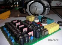
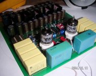
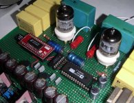
Attachments
") happy new year!
happy new year!Re: NEXT
Hi,
I just had a look. The Analog stage shown IMHO is not particulary suited to the AD1865 and worse, it actually requires a modification to work well for non-oversampling DAC's.
I originally concieved this circuit for modifications on the Philips CD720/21/22/23 and related (Philips CD71X and Marantz CD3000/4000 & CD36/46 et al) which are equipped with a TDA1545 DAC chip which requires it's output to be held at around 3V DC offset.
The AD1865 is unlikely to be too fond of 3V DC offset on the output.
The rest appears to be basically the Audio Note DAC Kit, re-drawn.
Sayonara
Hi,
xiaolong said:Electric circuit is this,
http://www.ptsoundlab.com/secnumerique/dac/mondac1865/zeroad1865n.htm
But this electric circuit contain mistake, just pass by to correct, the work is good
I just had a look. The Analog stage shown IMHO is not particulary suited to the AD1865 and worse, it actually requires a modification to work well for non-oversampling DAC's.
I originally concieved this circuit for modifications on the Philips CD720/21/22/23 and related (Philips CD71X and Marantz CD3000/4000 & CD36/46 et al) which are equipped with a TDA1545 DAC chip which requires it's output to be held at around 3V DC offset.
The AD1865 is unlikely to be too fond of 3V DC offset on the output.
The rest appears to be basically the Audio Note DAC Kit, re-drawn.
Sayonara
Re: Re: NEXT
The power supply is different.
Salut.
Kuei Yang Wang said:The rest appears to be basically the Audio Note DAC Kit, re-drawn.
Sayonara
The power supply is different.
Salut.
Hello
On this schematic, I can't understand the purpose of the NOR gates.
Some one can explain ?
Obviously, inverter are needed for LL and LR, but for me it's all.
Kuei Yang Wang :
I don't understand when you speak about offset. The analog part is only a second order filter, just after the 270 Ohms I/V converter.
Please, can you explain ?
Philippe
Hi Philippe., I guess it is kind of zeros stuffing thing with the 74HC02.philbyx said:Hello
On this schematic, I can't understand the purpose of the NOR gates.
Some one can explain ?
Obviously, inverter are needed for LL and LR, but for me it's all.
Kuei Yang Wang :
I don't understand when you speak about offset. The analog part is only a second order filter, just after the 270 Ohms I/V converter.
Pease, can you explain ?
Philippe
I don't feel called for to figure it out.
It also works with a 74HC04 (only one inverter used ) for the latch of one of the stereo channels. Been there done that.
Konnichiwa,
This is swiped straight from the AN Schematic. It does a bit more then merely inverting LE/Wordclock. One drawing error I noticed is that the line that should conncet to sdata connects to verf...
I am refering to the Valve based IV/LPF schematic further down, which BTW is a bit cheeky, as it marked ptsoundlabs and no credit is given to the source....
Basically this one:
It is designed to have ~3V on the first ECC88 cathode to match the TDA1545. The LPF Capacitor/Resistor Values are only applicable to Oversampling circuits, for non-oversampling they need to be changed to offset the Sin(X)/(X) rolloff.
If one wanted to use a similar circuit for DAC's that expect 0V DC on the output one should replace the cathode resistor by a CCS and apply (probably servo based) offset nulling to the grid.
Sayonara
philbyx said:On this schematic, I can't understand the purpose of the NOR gates. Some one can explain ?
This is swiped straight from the AN Schematic. It does a bit more then merely inverting LE/Wordclock. One drawing error I noticed is that the line that should conncet to sdata connects to verf...
philbyx said:I don't understand when you speak about offset. The analog part is only a second order filter, just after the 270 Ohms I/V converter.
I am refering to the Valve based IV/LPF schematic further down, which BTW is a bit cheeky, as it marked ptsoundlabs and no credit is given to the source....
Basically this one:
An externally hosted image should be here but it was not working when we last tested it.
It is designed to have ~3V on the first ECC88 cathode to match the TDA1545. The LPF Capacitor/Resistor Values are only applicable to Oversampling circuits, for non-oversampling they need to be changed to offset the Sin(X)/(X) rolloff.
If one wanted to use a similar circuit for DAC's that expect 0V DC on the output one should replace the cathode resistor by a CCS and apply (probably servo based) offset nulling to the grid.
Sayonara
Re: NEXT/ Error
Actually the output of the opamp must be able to reach -6.2V as the transistors are Darlingtons.
Also the 22µF cap at pin 2 of the lower opamp should be omitted.

Yes there is a mistake (drawing error) in the -5V supply The opamp should have pin 4 at some negative voltage in order to drive the pass-transistor.xiaolong said:Electric circuit is this,
http://www.ptsoundlab.com/secnumerique/dac/mondac1865/zeroad1865n.htm
But this electric circuit contain mistake, just pass by to correct, the work is good
Actually the output of the opamp must be able to reach -6.2V as the transistors are Darlingtons.
Also the 22µF cap at pin 2 of the lower opamp should be omitted.
The power supply supply is different .
The power supply is supplied and is used LT1086=+5V/-5V/VD5V
TUBE's high pressure is used LT1085 with TL783,'s filament
Http://www.ptsoundlab.com/secnumeri ...zeroad1865n.htm SDATA's signal of this picture does not meet and is right , still to have an error is CS8414 it does not set up into 18BIT,
Please that I am only be dead against the technology problem and point out has learned the guilt is forgiven
Wish that everybody is happy New Year once more
Hi,
I am looking for this DAC to build once, but couldn't find any English-speaking expert to ask, so I really like that it has appeared here. I decided long ago, that I will build an AD1865N-K based DAC, but couldn't find anything else (except a discontinued project).
I have some questions for you:
- Do you know a better DIY DAC using AD1865N-K?
- Earlier Kuei Yang Wang said
Do you think it is possible to implement I2S input and some reclocking circuit built into the board? For the I2S I heard that it is very difficult to convert the 16-bit format into 18-bit format used by the AD1865N-K, but I know it's possible. And, when using I2S input is it better to have non-reclocking DAC and a clock replacement in the source? Luckily, Kwak is here!
I hope you could help me solving those problems, because if we could make this project, we would produce diyaudio's best DAC (or best, for some personal taste).
I am looking for this DAC to build once, but couldn't find any English-speaking expert to ask, so I really like that it has appeared here. I decided long ago, that I will build an AD1865N-K based DAC, but couldn't find anything else (except a discontinued project).
I have some questions for you:
- Do you know a better DIY DAC using AD1865N-K?
- Earlier Kuei Yang Wang said
andThe Analog stage shown IMHO is not particulary suited to the AD1865 and worse, it actually requires a modification to work well for non-oversampling DAC's.
Is it possible to fix these problems? I am just a newbie in the DIY digital world, but I would like to build the most natural sounding DAC from available DIY plans, and I hope that this DAC could be a good starting point. If you don't think it is a problem to have it build using a PCB board, then I could draw it in some CAD program and have it built by a PCB printing professional (makes possible group-buying).It is designed to have ~3V on the first ECC88 cathode to match the TDA1545. The LPF Capacitor/Resistor Values are only applicable to Oversampling circuits, for non-oversampling they need to be changed to offset the Sin(X)/(X) rolloff. If one wanted to use a similar circuit for DAC's that expect 0V DC on the output one should replace the cathode resistor by a CCS and apply (probably servo based) offset nulling to the grid.
Do you think it is possible to implement I2S input and some reclocking circuit built into the board? For the I2S I heard that it is very difficult to convert the 16-bit format into 18-bit format used by the AD1865N-K, but I know it's possible. And, when using I2S input is it better to have non-reclocking DAC and a clock replacement in the source? Luckily, Kwak is here!
I hope you could help me solving those problems, because if we could make this project, we would produce diyaudio's best DAC (or best, for some personal taste).
Konnichiwa,
Not without really seriously re-designing the circuit.
The circuit was designed for TDA1545 (which BTW sound better than the AD1865 to my ears anyway) and ONLY for that specific chip. Unlike most other Tube stages it is not suitable to a "universal" application.
BTW, you can get a rather inexpensive DIY Dac for TDA1545, PCB & TDA1545 with postage should be below $ US40....
http://diyparadise.com/dackit/1545dackit.html
Then simply add the Tube Stage etc as I originally suggested here:
http://db.audioasylum.com/cgi/m.mpl?forum=tweaks&n=52708
The schematic that was originally linked is identical to this one:
The changes needed if the DAC is operated Non Oversampling (only changed values shown) are....
R2 = 100
R3 = 18k
R4 = 11k
R5 = 15k
R9 = 24K
C1 = 1n5 Silver Mica
C2 = 100p Silver Mica
C3 = 4n7 Silver Mica
The load on the Output Should ideally be 100K or higher.
The "super reg" for the TDA1545 Supply is this:
Both designs are originally mine and my actual drawings where presented by ptsoundlab.com WITHOUT permission or attribution BTW.
Sayonara
erozsolt said:- Earlier Kuei Yang Wang said and
Is it possible to fix these problems?
Not without really seriously re-designing the circuit.
The circuit was designed for TDA1545 (which BTW sound better than the AD1865 to my ears anyway) and ONLY for that specific chip. Unlike most other Tube stages it is not suitable to a "universal" application.
BTW, you can get a rather inexpensive DIY Dac for TDA1545, PCB & TDA1545 with postage should be below $ US40....
http://diyparadise.com/dackit/1545dackit.html
Then simply add the Tube Stage etc as I originally suggested here:
http://db.audioasylum.com/cgi/m.mpl?forum=tweaks&n=52708
The schematic that was originally linked is identical to this one:
An externally hosted image should be here but it was not working when we last tested it.
The changes needed if the DAC is operated Non Oversampling (only changed values shown) are....
R2 = 100
R3 = 18k
R4 = 11k
R5 = 15k
R9 = 24K
C1 = 1n5 Silver Mica
C2 = 100p Silver Mica
C3 = 4n7 Silver Mica
The load on the Output Should ideally be 100K or higher.
The "super reg" for the TDA1545 Supply is this:
An externally hosted image should be here but it was not working when we last tested it.
Both designs are originally mine and my actual drawings where presented by ptsoundlab.com WITHOUT permission or attribution BTW.
Sayonara
And what do you think about this:
http://www.rockna-line.com/diy/dac/dac.htm
Anyway, I beleive you, what do you suggest for the best I2S capable high-end like DIY DAC? I have mixed opinions about TDA1545, and I really don't know which one to build.
http://www.rockna-line.com/diy/dac/dac.htm
Anyway, I beleive you, what do you suggest for the best I2S capable high-end like DIY DAC? I have mixed opinions about TDA1545, and I really don't know which one to build.
Better than AD1865N-K?
I have been using the AD1865N-K for quite some time but eventually switched to the TDA1543 NON-OS because I liked it more.
It is possible to convert Philips I2S format to 18 bits including two zeros but you can put the CS8412 into the 18-bits output format.
If you are working with I2S Direct I do not recommend (asynchronous) reclocking as the jitter in the SPDIF interface is omitted.
For good sound the masterclock in the source (the player) should always be replaced!
I have built various DACs like PCM56, AD1851, AD1864, AD1865N-K, TDA1541AS1 and TDA1545, all NON-OS.
Hi erozsolt,erozsolt said:
- Do you know a better DIY DAC using AD1865N-K?
-
Do you think it is possible to implement I2S input and some reclocking circuit built into the board? For the I2S I heard that it is very difficult to convert the 16-bit format into 18-bit format used by the AD1865N-K, but I know it's possible. And, when using I2S input is it better to have non-reclocking DAC and a clock replacement in the source? Luckily, Kwak is here!
I have been using the AD1865N-K for quite some time but eventually switched to the TDA1543 NON-OS because I liked it more.
It is possible to convert Philips I2S format to 18 bits including two zeros but you can put the CS8412 into the 18-bits output format.
If you are working with I2S Direct I do not recommend (asynchronous) reclocking as the jitter in the SPDIF interface is omitted.
For good sound the masterclock in the source (the player) should always be replaced!
I have built various DACs like PCM56, AD1851, AD1864, AD1865N-K, TDA1541AS1 and TDA1545, all NON-OS.
Konnichiwa,
Same AD1865. I heard it in the AN DAC's and I don't like it.
Don't. As you can see reading the thread, Elso likes the polar opposite from what I like. His list of likes and less liked reads in almost exactly reverse order to mine, plus he likes to roll the high frequencies in the DAC off well past that which is natural in a non-oversampling DAC, while I like to restore them to parity with lower frequencies as one would experience with more conventional circuits.
TDA1541 correctly implemented. It is the best one in my view even if we include non I2S capable ones.
Simple, build them all.
Here my list of what I like, based strictly on replay of prerecorded CD's and on having worked with them:
1) TDA1541 Double Crown
2) TDA1541 Single Crown
3) TDA1541 normal
4) PCM56
4) PCM63
4) TDA1545
5) PCM1702
5) PCM1704
6) Pioneers older "Legato Link" bitstream DAC's (not sure who made them, they now use customised BB hybrid DAC's, YUCK)
7) TDA1543
9) NPC Delta Sigma DAC's (SM5872, 5864) correctly implemented
I do not like much any of the burr brown "hybrid" DAC's, never really liked the AD Multibit converters either, hate the Cirrus Logic and AKM DAC's. Note that some of these DAC's have build in digital filters.
Only TDA1541 & TDA1543 from this list are directly I2S compatible and non-os. The others require the Sony Format.
Sayonara
erozsolt said:
Same AD1865. I heard it in the AN DAC's and I don't like it.
erozsolt said:Anyway, I beleive you,
Don't. As you can see reading the thread, Elso likes the polar opposite from what I like. His list of likes and less liked reads in almost exactly reverse order to mine, plus he likes to roll the high frequencies in the DAC off well past that which is natural in a non-oversampling DAC, while I like to restore them to parity with lower frequencies as one would experience with more conventional circuits.
erozsolt said:what do you suggest for the best I2S capable high-end like DIY DAC?
TDA1541 correctly implemented. It is the best one in my view even if we include non I2S capable ones.
erozsolt said:I have mixed opinions about TDA1545, I really don't know which one to build.
Simple, build them all.
Here my list of what I like, based strictly on replay of prerecorded CD's and on having worked with them:
1) TDA1541 Double Crown
2) TDA1541 Single Crown
3) TDA1541 normal
4) PCM56
4) PCM63
4) TDA1545
5) PCM1702
5) PCM1704
6) Pioneers older "Legato Link" bitstream DAC's (not sure who made them, they now use customised BB hybrid DAC's, YUCK)
7) TDA1543
9) NPC Delta Sigma DAC's (SM5872, 5864) correctly implemented
I do not like much any of the burr brown "hybrid" DAC's, never really liked the AD Multibit converters either, hate the Cirrus Logic and AKM DAC's. Note that some of these DAC's have build in digital filters.
Only TDA1541 & TDA1543 from this list are directly I2S compatible and non-os. The others require the Sony Format.
Sayonara
Dear Kuei Yang Wang,
I had one question, Do U had any experience which compare the sound quality about 1541a NON-oversampling & PCM56 NON-oversampling.
thx
thomas
Here my list of what I like, based strictly on replay of prerecorded CD's and on having worked with them:
I had one question, Do U had any experience which compare the sound quality about 1541a NON-oversampling & PCM56 NON-oversampling.
thx
thomas
Dear Kuei Yang Wang,
any comment for PCM67P??
http://www.alldatasheet.co.kr/datasheet-pdf/view/BURR-BROWN/PCM67P.html
thx
thomas
any comment for PCM67P??
http://www.alldatasheet.co.kr/datasheet-pdf/view/BURR-BROWN/PCM67P.html
thx
thomas
- Status
- This old topic is closed. If you want to reopen this topic, contact a moderator using the "Report Post" button.
- Home
- Source & Line
- Digital Source
- AD1865N-K nos DIY