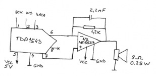
I'm trying to make some kind of a soundcard for my ATMEGA8 AVR microcontroller. For that I got a TDA1543 and a NE5532, wired them as in the datasheet schematic (tda's Vref to the noninverting input of the 5532, AOL to inverting input, feedback resistor) and expected to work. Well, it doesn't.
I tried sending the whole range (-32000 to 32000) to both left and right channels. I get something strange. Between -32000 and -14000 (aprox. values) the voltage lowers from 1.69V to 1.48V, then goes up to 2 V, then lowers to 1.48 (at 18000), goes back to 2 then to 1.69 (at 32000).
From this I guess I haven't understood the i2s protocol right .
.
I'd like to see some code implementation (C, pseudocode, I don't care) because I don't understand a thing from those electrical diagrams. I mean in the datasheet they say that the MSB must be sent first, but in the datasheet after switching the WS line, it first sends the LSB of the previous value, then the MSB of the current value. The LSB of the current value will be sent after switching the WS again. It's wierd, I'm sure I'm missing something.
Please, help!
P.S. I'm using single-supply for the 5532 (+5V and 0V). Do you thing it has anything to do with this?
I tried sending the whole range (-32000 to 32000) to both left and right channels. I get something strange. Between -32000 and -14000 (aprox. values) the voltage lowers from 1.69V to 1.48V, then goes up to 2 V, then lowers to 1.48 (at 18000), goes back to 2 then to 1.69 (at 32000).
From this I guess I haven't understood the i2s protocol right
.I'd like to see some code implementation (C, pseudocode, I don't care) because I don't understand a thing from those electrical diagrams. I mean in the datasheet they say that the MSB must be sent first, but in the datasheet after switching the WS line, it first sends the LSB of the previous value, then the MSB of the current value. The LSB of the current value will be sent after switching the WS again. It's wierd, I'm sure I'm missing something.
Please, help!
P.S.
I'm using single-supply for the 5532 (+5V and 0V). Do you thing it has anything to do with this?1. Is the data in the two's complement ?
2. What is the value of Vref at the + inputs ? it should be around 2.5v
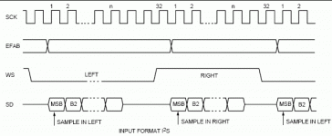
The image below shows an I2S diagram with serial clock running at 64Fs ie 32 bits per frame. Note the position of the lsb of the left channel frame.
2. What is the value of Vref at the + inputs ? it should be around 2.5v
The image below shows an I2S diagram with serial clock running at 64Fs ie 32 bits per frame. Note the position of the lsb of the left channel frame.
Attachments
1. Yes, the data is in two's complement.
2. The value of Vref is 2.15 V, measured in this schematic.
I don't know... Maybe it's because the first thing I'm sending after switching the WS is the MSB of the current value, instead of the LSB of the previous one.
The data is retained on the LO->HI transition of the BCK, right?
BTW: Merry Christmas!
Attachments
fili said:I don't know... Maybe it's because the first thing I'm sending after switching the WS is the MSB of the current value, instead of the LSB of the previous one.
The data is retained on the LO->HI transition of the BCK, right?
BTW: Merry Christmas!
I2S data is valid on the rising edge of BCK/SCK
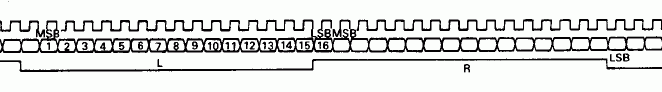
What get transmitted after the transition of WS depends on the size of the frame. If the frame is only 16bits per channel then all 16 audio data bits occupy the entire frame. WS is the same size as the frame i.e low for 16 bits or 16 SCK transitions and high for the same time. The MSB of the audio word is aligned with the second transition of SCK that occurs after a transition of WS, for the left channel that would be a falling edge. For a 16 bit per channel frame size, that would align the LSB of the left channel word with first transition of SCK that occurs after a transition of WS, in this case a rising edge.The MSB of the right channel word follows immediately afterwards aligning it with second transition SCK that occurs after the rising edge of WS.
In other words, it looks like this.
Attachments
fili said:Ok, I'll modify the algorithm to use only the first 15 bits, so that the LSB will always be 0. This way I solve some problems. I only hope it works...
Not sure what you mean but the position of the MSB relative to WS is fixed in the I2S spec. When I needed an audio word generator it was so much easier in programmable logic. For a micro the sequence would be something like this:-
Clear WS
Clear Sck
Send 16th R bit i.e. LSB, to port. End of L/R word 1
Set Sck
Clear Sck
Send 1st L bit i.e. MSB, to port. Start of L/R word 2
Set Sck
.
.
.
.
Clear Sck
Send 15th L bit
Set Sck
Set WS
Clear Sck
Send 16th L bit. Left channel LSB
Set Sck
Clear Sck
Send 1st R bit. Right channel MSB
Set Sck
.
.
.
.
Clear Sck
Send 15th R bit
Set Sck
Clear WS
Clear Sck
Send 16th R bit. Right channel LSB. End of L/R word 2
Set Sck
Clear Sck
Send 1st L bit. Start of L/R word 3
Set Sck
.
.
Hi,
I have bought several TDA1543 with the phiplis logo and also TDA1543 with
PNO logo. Now I have change the TDA1543 with an TDA1543 I have bought and only loud noise.
the original one has also an Philips logo the last one
the others only noise....
i don't know why, but it seems there are different type of format
how can i see the difference?

.jpg")

I have bought several TDA1543 with the phiplis logo and also TDA1543 with
PNO logo. Now I have change the TDA1543 with an TDA1543 I have bought and only loud noise.
the original one has also an Philips logo the last one
the others only noise....
i don't know why, but it seems there are different type of format
how can i see the difference?
- Status
- This old topic is closed. If you want to reopen this topic, contact a moderator using the "Report Post" button.
- Home
- Source & Line
- Digital Source
- Tda1543