Hi guys and gals!
i´m looking for schematics and possibly software (.hex/.asm) for PIC16F84 or similar..
what do i want it to do?
*switch at least between two different inputs (..relay of course)
*a power-up timer for switching on the tube powersupply (delay ~40 seconds or so..)
*mute switch
so there will be a count of 3-4 button inputs and about 4 outputs on the PIC
any links?
anybody who would like to write a program for me?
-i can program the PIC myself so all i need is the proper code in hex or asm
any help appreciated!!
Banned
Joined 2002
Banned
Joined 2002
hi neteagle!
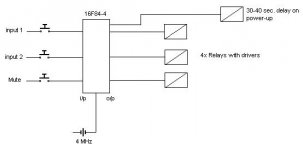
what i want the pic (16F84-4) to do is this;
*at power-up there should be a delay on one pin, about 30-40 seconds, for the tube powersupply or speaker switch-on if used in a power amplifier
(in that way this circuit would be universal for DIY tubes, preamps or amps..)
*two buttons for switching between two inputs (CD/TAPE)
that is two inputs and two outputs from the pic
*one button for mute or any other function i would like, one input and one output on the pic
i would like to use momentary switches, so the output from the pic should change state everytime i press the button, the button should be de-bounced with 20ms or so..
i attached a simple schematic over the PIC with the buttons
as you can see there would be a total count of three inputs and four outputs (it can be simplified thrue only using one button for switching between the two inputs)
Attachments
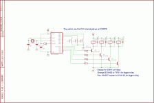
No problem - that's also the reason I wrote my own code from scratchMr. Triatic said:but i´m somewhat stubborn, i still want to use a pic processor, in that way i can modify the code and maybe learn myself how to write my own code someday
But the schematics may be of some help...
Best regards,
Mikkel C. Simonsen
hmm... im not sure of what you mean with the "intensity" of the coil??
but:
on power-up, a timer counts to 30-40 seconds and then pulls the RA4 high (and the relay, used to switch on PSU for tubes or speaker-out relay)
S1 - pulls the RA1 relay immiedatly and releases it when S1 are pressed again (as for a mute function)
S2 - pulls the RA2 relay (if not S3 is pushed)
S3 - pulls the RA3 relay (if not S2 is pushed)
S2 and S3 shall not be able to be at the same state at the same time (they are to be alternating..)
is that a possible way to program the circuit?
.ASM would be preffered i think, i can assemble it myself i have figured out how the MPASM software works
Huge thanks in advance Neteagle!!
but:
on power-up, a timer counts to 30-40 seconds and then pulls the RA4 high (and the relay, used to switch on PSU for tubes or speaker-out relay)
S1 - pulls the RA1 relay immiedatly and releases it when S1 are pressed again (as for a mute function)
S2 - pulls the RA2 relay (if not S3 is pushed)
S3 - pulls the RA3 relay (if not S2 is pushed)
S2 and S3 shall not be able to be at the same state at the same time (they are to be alternating..)
is that a possible way to program the circuit?
.ASM would be preffered i think, i can assemble it myself
i have figured out how the MPASM software works Huge thanks in advance Neteagle!!
looks nice, i will test it in-circuit when i'm off for the day, working right now, but i will report as soon as i have tested the code!!
Huge thanks again Neteagle!!
BTW, can i publish the code on my homepage together with the schematic for my preamp, of course with creds to you for the code?
Huge thanks again Neteagle!!
BTW, can i publish the code on my homepage together with the schematic for my preamp, of course with creds to you for the code?
- Status
- This old topic is closed. If you want to reopen this topic, contact a moderator using the "Report Post" button.
- Home
- Source & Line
- Digital Source
- control a preamp with PIC-processor