Hi All,
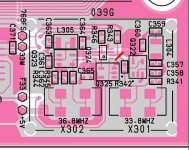
Have bought XO2 Clock and XO Power Supply. Now, after removing the copper shielding from the system clock assembly of my Marantz CD-7, I find two SMD mounted KDS clocks. One reads KDS 8D 36,864MHz and the other one reads KDS 0D 33, 868MHz. And a lot of SMD r's and c's surrounding it.
Has anyone got the CD-7 schematics or experience in replacing the clock?
Thanks in advance.
Kind Regards,
Ramon
The Netherlands
An externally hosted image should be here but it was not working when we last tested it.
An externally hosted image should be here but it was not working when we last tested it.
An externally hosted image should be here but it was not working when we last tested it.
An externally hosted image should be here but it was not working when we last tested it.
An externally hosted image should be here but it was not working when we last tested it.
An externally hosted image should be here but it was not working when we last tested it.
Hi all,
Elso provided me with a schematic of the CD-7. Thanks again Elso!!!
Now one more question:
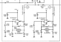
My CD-7 has two clocks, one for 18 bit and one for 16 bit operation i think. Below are the schematics
I Think i need to remove c357 and c358, and the x301 clock off course. Then connect the new clock over the resisitor r341. But does it matter where the black and purple wire of the new clock are fitted?
Thanks
Elso provided me with a schematic of the CD-7. Thanks again Elso!!!
Now one more question:
My CD-7 has two clocks, one for 18 bit and one for 16 bit operation i think. Below are the schematics
I Think i need to remove c357 and c358, and the x301 clock off course. Then connect the new clock over the resisitor r341. But does it matter where the black and purple wire of the new clock are fitted?
An externally hosted image should be here but it was not working when we last tested it.
Thanks
Attachments
Remove L304 and C359. Remove R341 and R342, X301, C357 and C358 and finally remove Q322.In short, remove all circuitry around Q322 ") You can leave C360 where it is.
You can leave C360 where it is.
Now connect the output of the new clock to where pin 4 of Q322 was before or use the upper connection where R342 was when that is more convenient. The left leg of R343 is a possibility too. I do not know this famous cdplayers insides well so check the most convenient spot yourself. The shorter the wires from the clock to the pcb the better.
Although familiar with Tent clocks I can't tell what colour the output wire is but I am confident that a manual was shipped with the clock which can explain that.
Please do not screw up this beautiful piece of technology by accident. Although I don't have much time I am willing to advise you more or to do the job for you in case you are uncertain if you'll succeed.
You can leave C360 where it is.Now connect the output of the new clock to where pin 4 of Q322 was before or use the upper connection where R342 was when that is more convenient. The left leg of R343 is a possibility too. I do not know this famous cdplayers insides well so check the most convenient spot yourself. The shorter the wires from the clock to the pcb the better.
Although familiar with Tent clocks I can't tell what colour the output wire is but I am confident that a manual was shipped with the clock which can explain that.
Please do not screw up this beautiful piece of technology by accident. Although I don't have much time I am willing to advise you more or to do the job for you in case you are uncertain if you'll succeed.
Hi,
Thanks for your excellent detailled response!
I will definately not screw up the CD-7, trust me ;-)
Have repaired a lot of good old Marantz amps, but never with smd technology.
As the schematic from the mounting manual Guido provided me with shows, he advises only to remove both 12pF capacitors and the clock.
Why do you advise to remove everything including the servo IC?
Kind regards,
Ramon
Attachments
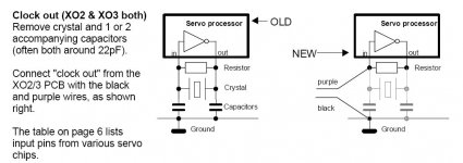
Guidos advice is for servo ICs that connect the XOout internally to other circuitry. So no possibility to connect a new clock internally to that circuitry.... Indeed this schematic applies to 99% of cdplayers. Except CD7
The oscillator as used in the CD7 is more or less discrete built and it is better to omit it alltogether and to connect the new clock to the point where the old clock outputted its signal to. Q322 is NO servo IC but a inverter in a SMD case.
As I see it the purple wire of the Tent clock is output.
The oscillator as used in the CD7 is more or less discrete built and it is better to omit it alltogether and to connect the new clock to the point where the old clock outputted its signal to. Q322 is NO servo IC but a inverter in a SMD case.
As I see it the purple wire of the Tent clock is output.
OK...
I guess cutting the trace at piont 23 would be easiest, (if you can find a place it will be easy to reverse the mod), then connect the new clock in the split-point...
This way you can leave the original clock intact.
(You could ofcourse cut the 5V supply to it, if you fear interference)
Arne K
I guess cutting the trace at piont 23 would be easiest, (if you can find a place it will be easy to reverse the mod), then connect the new clock in the split-point...
This way you can leave the original clock intact.
(You could ofcourse cut the 5V supply to it, if you fear interference)
Arne K
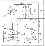
Sorry Arne, this was not the complete assembly.
Below are the pics of the complete assembly of the clock.
Is it correct to conclude to cut the connection just before were 23 splits in to line to F11 and line to R343?
Below are the pics of the complete assembly of the clock.
An externally hosted image should be here but it was not working when we last tested it.
Is it correct to conclude to cut the connection just before were 23 splits in to line to F11 and line to R343?
Attachments
D.A.R.R.Y.L. said:
I Think i need to remove c357 and c358, and the x301 clock off course. Then connect the new clock over the resisitor r341. But does it matter where the black and purple wire of the new clock are fitted?
An externally hosted image should be here but it was not working when we last tested it.
Thanks
Hi
The best you could do is forghet the inverter at all (its' power supply induces jitter)
Interrup the output from that inverter, and directly couple the output of XO2 (purple wire) to the line called " 23"
succes
Guido


Hi D.A.R.R.Y.L.
There are TWO separate clocks: 33.8688 MHZ and 36.8644 MHz.
ONLY ONE is used at the time, depending on F33 signal being HIGH or LOW. However, 33.8688 MHz clock is ALWAYS used for (probably) transport section's servo via R343 - can not tell from provided diagram – need more info!!!
For the best results you'll need two clocks - use the XTALs from your CD7. You'll need two separate power supplies as well, one for each clock!
You could modify only 33.8688 MHz clock. Again, for the best results you'll need a clock with two buffered outputs (main buffered output, and the second buffered output): feed main clock output to pin 2 of Q324 and the second buffered output to R343. CUT THE PCB TRACES as close to pin 2 of Q324 as possible and feed the signal straight to the pin2 of Q324IC!!!!
Lift LEFT side of R343 resistor and feed second clock output to this resistor. IT IS IMPORTANT to lift left side of this resistor to isolate traces influence (antennas!) to second buffered clock signal.
Now, remove Q322 to prevent jitter feed from Q322 back via +5V line. Better solution would be to cut +5V line feed to this Q322 IC as close to pint of origin as possible!
I am not sure why this CD player uses two clock frequencies. However, you could monitor F33 line and figure when and why the 33.8688MHZ clock is used, and when 36.864MHz signal is used. This could be selectable from your remote control or something. Find out how is this done and come back to me because I have a suggestion of an EXTREME_MOD for you if the player (and you!) use ALWAYS only ONE CLOCK frequency – 33.8688MHz. If this was the case, it is possible to ignore ALL 4 ICs. Clean-up your +5V tremendously and feed clock signals to LIFTED left hand sides of R346 and R343 – and that’s it!!!!
But first, let us be sure that in the case of Extreme_Mod, 36.864MHz clock signal WOULD NEVER BE NEEDED!!!!
USE ONLY SEPARATE (stand-alone) POWER SUPPLY FOR ALL YOUR CLOCK APPLICATIONS. DO NOT use CD’s power supply!!!!
Cheers,
Nick
- Status
- This old topic is closed. If you want to reopen this topic, contact a moderator using the "Report Post" button.
- Home
- Source & Line
- Digital Source
- Marantz CD-7 + XO2 clock and XO Supply