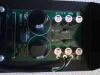
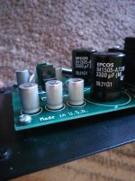
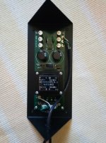
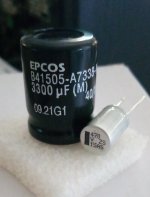
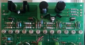
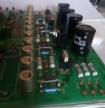
back when these units were designed c. 1990, the polymer electros didn't exist, and electrolytics of that time didn't have good performance at ultrasonic / low Mhz frequencies.
adding just the 2nd trim (half msb) might be worthwhile. and / or upgrading the I-V conversion op-amps but be careful of using OPA627 and other high-BW units without adequate / effective power rail bypassing (capacitor leads need to be kept very short)
adding just the 2nd trim (half msb) might be worthwhile. and / or upgrading the I-V conversion op-amps but be careful of using OPA627 and other high-BW units without adequate / effective power rail bypassing (capacitor leads need to be kept very short)
Last edited:
I HATE this board. What a POS!
Anyway, I have all four tantalums replaced with the new ones. Since my last post, I have learned all tantalum caps have a 50% derating. The old ones were close; new ones have a significant margin. Plus tighter tolerance.
I hope to test a bit over the holiday, time permitting.
And again, I forsake the 12 filter caps because the board is such crap. Thin plating that is not through plated… many pads and traces lifted from original assembly (looks worse on the underside!)
Anyway, I also have parts for the eBay DAC from ten years ago. I am going to stick with op amps but I selected a few replacements that will very easily outperform the original bottom feeders in there. I’m saving the transformers for something else.
The final chapter of this saga is a plan for a dual-mono ESS ES9038pro chip DAC. I like the specs on this chip, especially with all eight channels paralleled and a fully balanced architecture.
Hi, Jim.Anyway, I have all four tantalums replaced with the new ones. Since my last post, I have learned all tantalum caps have a 50% derating. The old ones were close; new ones have a significant margin. Plus tighter tolerance.
I too am working on a D2A2 MkII found used.
For the moment I have changed the capacitors to the IPS.
I will soon be working on the DAC, starting with the 3300 uF and 470 uF capacitors (for the latter I will use organic polymer capacitors).
A question; from the diagram above it seems to me that the tantalum capacitors are 4.7 uF / 35V: can you confirm this for me?
Which tantalum capacitors have you used?
I thank you in advance.
Bachisio
Sorry, he ran away ... a 2!Mine is not the D2A2 but the first gen D2A. So, your requirements may be different.
I went much higher on voltage and tight tolerance (1% maybe?). Same value as original.
Shop Mouser and you can filter to find what you need.
The only difference - mine is the MkII - is the add-in pcb.
So the value is 4.7 uF?
Perfect...The schematic was correct. I don’t recall the value off the top of my head.
I asked you because in the Dac in my possession there are 4 electrolytic capacitors instead of tantalum capacitors.
Furthermore, their value is 10 uF.
C24 is also an electrolytic capacitor (4,7 uF/100V), contrary to what appears in some photos of the interior of the Dac.
And it doesn't seem like they've been changed ... hi-fi mysteries ...
Desoldering the capacitors from the main board of the Dac was more difficult than the IPS. Perhaps due to the overall quality of the Pcb not exceptional, perhaps due to the excessive use of flux in soldering, perhaps because someone else had already put their hand to the dac (bought used), i think that without the desoldering gun i would not have done it.
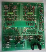
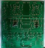


Obviously, the replacement of the electrolytics could not fail to be accompanied by that of the "infamous" polypropylene capacitors.
I'm kidding, of course...
I do not think it is correct to attribute all the - presumed - defects of the Dac to these components.
However, without spending much, I found in the Mouser catalog some ICEL components - with recognized good value for money - marketed by Nichicon. I think there is a very good chance that they ar an improvement over the (however honest) ones provided.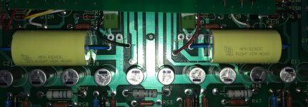

Given that the capacitors (C5, C6 and C24) identified were - contrary to what is depicted in many images of the D2A PCB - electrolytic and that the main purpose of using the tantalum ones would have to lie in the low ESR, I replaced those found with organic polymer capacitors. I used the Kemet A759s.
I have successfully used organic polymer capacitors in the maintenance of other DACs (Musical Fidelity Digilog and Thule Audio DAC200).
I do not intend to question, of course, the intention of the designers; however, I must note that in other circumstances (such as in the Digilog) the use of tantalum capacitors affects voltages lower than those in the main PCB of the D2A. Without neglecting the intentions of the designer (low ESR), I find it more reassuring to limit the use of tantalum capacitors to the digital section, affected by lower voltages.
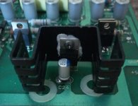
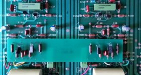


Last edited:
- Home
- Source & Line
- Digital Source
- Aragon D2A upgrade path?
