Hi there
I need help indentifying some detalis in my Denon DCD3300 CD player.
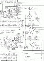
The attached gif file shows the first steps (Super Linear Converters of L and R channel) that follow immediately after the outputs pins from the DAC chips (lead 3 in CB702 and CB752).
Then comes the Low Pass Filter (3 coils and C123,124,125) of the L channel and then the L channel output buffer opamp (IC106 = NE5532, pin 7 goes directly to the RCA out socket L channel. R channel not shown).
The opamps in each of the blocks 2U1435 are in fact also NE5532 (only ½ of each is used).
I would like to know what is the purpose of the NE5532 in the two blocks 2U1435?
My guess is that it is I/V converting circuits between the DAC chips and the Low Pass Filter (3 coils and C123,124,125) but I am not sure.
I have read that replacing the NE5532 opamps in the buffer stage (IC106) by e.g. AD825 modules should be a good idea.
http://www.audiocominternational.co...cat&strKeywords=&strSearchCriteria=&PT_ID=103
But if the opamps in each of the blocks 2U1435 are also NE5532, should they also be replaced by AD825 modules or is the quality of the opamps here of no importance?
Attachments
I'd guess that those opamps in 2U1435 are even more critical, since they're handling higher-bandwidth signals, right?
Is this CD player from the 80's? I seem to remember that the Japanese decks were into high-order passive filters back then, which tended to ring when reproducing square waves. Whether that was supposed to have any audible consequences, I don't remember. Anyway, the pictures of square waves from oversampling decks like Philips looked a lot cleaner.
Is this CD player from the 80's? I seem to remember that the Japanese decks were into high-order passive filters back then, which tended to ring when reproducing square waves. Whether that was supposed to have any audible consequences, I don't remember. Anyway, the pictures of square waves from oversampling decks like Philips looked a lot cleaner.
The Denon DCD3300 is from 1987. What makes this deck so remarkable is the transport mechanism which is rock solid and contributes to the sound of this machine. I put a new reference clock (LC Audio LClock XO 3) in it and replaced the IC106=NE5532 with LC Audio's AD825 based opamp module (same as the audiocominternational.com product) and it sounds great! Much more fine grained sound and remarkably better soundstage.
I wonder whether replacement of the NE5532 in the 2U1435 circuits with some other opamp would be beneficial.
I wonder whether replacement of the NE5532 in the 2U1435 circuits with some other opamp would be beneficial.
As i read it it is a voltage buffer, provided that the opamp is a voltage feedback opamp. A high quality discrete buffer here would be nice.
My guess is that it is there to isolate the DAC from the varying load of the filter.
Selection criteria for the OPAMP would be ultra high bandwidth and low settling time since it is coupled before the LPF filter.
Do you know if it is a current output dac?
My guess is that it is there to isolate the DAC from the varying load of the filter.
Selection criteria for the OPAMP would be ultra high bandwidth and low settling time since it is coupled before the LPF filter.
Do you know if it is a current output dac?
And further from the datasheet:
FEATURES
SERIAL INPUT
–92dB MAX THD: FS Input, K Grade
–74dB MAX THD: –20dB Input, K Grade
96dB DYNAMIC RANGE
NO EXTERNAL COMPONENTS REQUIRED
16-BIT RESOLUTION
15-BIT MONOTONICITY, TYP
0.001% OF FSR TYP DIFFERENTIAL LINEARITY ERROR
1.5ms SETTLING TIME, TYP: Voltage Out
±3V OR ±1mA AUDIO OUTPUT
EIAJ STC-007-COMPATIBLE
OPERATES ON ±5V TO ±12V SUPPLIES
PINOUT ALLOWS I-OUT OPTION
PLASTIC DIP OR SOIC PACKAGE
DESCRIPTION
The PCM56 is a state-of-the-art, fully monotonic,
digital-to-analog converter that is designed and
specified for digital audio applications. This device
employs ultra-stable nichrome (NiCr) thin-film
resistors to provide monotonicity, low distortion, and
low differential linearity error (especially around
bipolar zero) over long periods of time and over the
full operating temperature.
This converter is completely self-contained with a
stable, low noise, internal zener voltage reference;
high speed current switches; a resistor ladder network;
and a fast settling, low noise output operational
amplifier all on a single monolithic chip. The
converters are operated using two power supplies that
can range from ±5V to ±12V. Power dissipation with
±5V supplies is typically less than 200mW. Also
included is a provision for external adjustment of the
MSB error (differential linearity error at bipolar zero)
to further improve total harmonic distortion (THD)
specifications if desired. Few external components
are necessary for operation, and all critical
specifications are 100% tested. This helps assure the
user of high system reliability and outstanding overall
system performance.
Now I think I understand something:
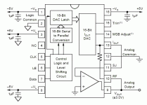
There is a I out option (PIN 13) and a low noise output operational amplifier (input PIN 13, output PIN 9).
I assume that the I/V conversion is taken care of internally by the "noise output operational amplifier ".
Or am I still wrong here?
My question is still whether there is a better opamp than NE5532P for the 2U1435 circuit.
A NE5534 (single opamp) would require a different pin connection scheme, and maybe other component values (R701, R702 and R703).
Attachments
The IV conversion is done by the internal opamp yes.
Question is if that isn't where you should put your effort if you want to upgrade the quality of the device. I.e pull the current out signal instead and forget the internal opamp.
Yes there are better opamps for the buffer, it is a buffer nothing else.
The question on which is the best one is a religious one.
Some say AD797 is the one others AD8610 (8620 for double).
Some like the BB(2)604 BB(2)134 and so on.
Personally i would build a discrete buffer for this application.
First of all thank you Hjelm for helping me!
Yes Hjelm, the 2U-1435 "modules" are mounted on one separate PCB with wires for +/- 15 V power supply (CB701/CB751 connectors) and wires for signal from DAC chips and wires for output from 2U-1435 to LPF (CB702/CB752 connectors). The opamps in the 2U-1435 are NE5532P of which only ½ are used (strange, why not use NE5534).
Are you able to tell why the 2U-1435 "modules" are mounted separately in stead of just putting all the components directly on the main board?
OK, so the NE5532P in the 2U-1435 "modules" are gain=1 buffers.
Then the following NE5532P (IC106) is another buffer for connection directly to the output RCA socket (left ch, right ch similar).
I may ask stupid questions but try nevertheless: Why is the signal going through IC106 before it goes to the RCA output socket? Why not directly from NE5532 in the 2U-1435 modules to the RCA output sockets?
OOOPs!
I wrote: I may ask stupid questions but try nevertheless: Why is the signal going through IC106 before it goes to the RCA output socket? Why not directly from NE5532 in the 2U-1435 modules to the RCA output sockets?
Because there is a low pass filter to take into consideration! Glad I found the answer myself!
But I still want to know why the 2U-1435 modules arew on a separate board.
klitgt said:OOOPs!
I wrote: I may ask stupid questions but try nevertheless: Why is the signal going through IC106 before it goes to the RCA output socket?
Because IC 106 provide , by mean of the relays , the de-emphasis in case of the disc has been recorded ,with pre-emphasis.
The lower part of IC 106 is a servo.
After all the manufacturers like to complicate the things a bit...
Jorge,
Thank you, it cleared things up a bit.
Could you help me further?
The IC106 (left ch) is NE5532P and may be replaced by AD825 based opamp modules.
In the 2U-1435 circuits are also NE5532P, but only ½ of the opamp is in use. I wonder whether these opamps may be replaced by AD825 modules. Or is there another opamp suitable for this?
The NE5532Ps in the 2U-1435 circuits get signal from IV converter and sends it to Low Pass Filter.
The 2U-1435 circuits are placed on a separate board, not on the main DAC board like IC106. Why not integrated on the main board?
The de-emphasis managed by IC106 is maybe important?
If I replace the entire analog stage by LC Audio Zapfilter mk.ll which takes its signal directly from the DAC chip I-out, will I disable the de-emphasis feature managed by the IC106?
So is it recommendable not to replace the entire analog stage?
Attachments
I have actually no idea why the 2u-1435 is on a separeate board. It seems they must have a reason since companys does not do anything that costs extra money if they do not have to. As for replacing the circuit with another opamp. Yes it is fully possible but if you use a single opamp to replace the double one you have to rearrange the pins. Easiest is to replace it with a double opamp.
Why they use a double onbe instead of a single one could be that it would cost more to buy a double one, it is all in the volumes.
Why they do not use both opamps and one module, guessing crosstalk or interference problems.
Why they use a double onbe instead of a single one could be that it would cost more to buy a double one, it is all in the volumes.
Why they do not use both opamps and one module, guessing crosstalk or interference problems.
Hi Hjelm,
Hi-Fi products require some fine-tuning before they are released from R&D departments in to Production. This involves different TYPES of ICs, resistors and capacitors. Certain combinations give good results. This is probably why 5532 OP amp is on a separate board(s).
You should definitely try AD826 (and OP275). Unfortunately, your CD player has + and - 15V DC for analogue stage, which prevent use of outstanding AD8066 (with adaptor boards).
Nick
- Status
- This old topic is closed. If you want to reopen this topic, contact a moderator using the "Report Post" button.
- Home
- Source & Line
- Digital Source
- Neede help identifying details in a diagram


