For a long time now, I have thourght about why anyone hasn't tried to replace the laserdiode itself on a CDM mechanism. Why? - For obvious reasons. Spare CDM mechanisms are getting harder and harder to find and 99.999% times a mechanism fails are because of the laser had died.
I had a CDM-4 arround which are skipping. I used it for a little 'test'. I don't have any spare laserdiodes arround, so I decided to try remove the old LED and re-inserting it again.
I can't say my first attempt was entierly sucessfull, but I managed to get the job done!
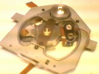
First step was to desolder the LED from the flexband. The flexband won't cripple or burn because of the heat. I used my soldering station set at 250 deg C. The first picture is showing that. I managed to break one of the soldering pads off the flexband. A small piece of wire was later used to 'fix' that.
Pictures at: http://cdmsurgery.diyaudio.dk/
The next step was to remove the LED. I turned the soldering station to 400 deg C. I used the heat and and a thin scalpel to remove it. The LED is held by two blobs of glue only.
Lastly, I re-inserted the LED and soldered the flexband in place. If I didn't break the solder pad it would have been easier.
This is my first (and probably anyone's) attempt to hack a CDM transport. I re-installed the drive in a crappy Philips cd164. When powered and no CD inserted, the motor spins, the arm moves and I can see a red light from the lens. The display then reads 'no disc'. - So far, so good. With a CD in the drive, it searches around for a while and then, the display reads 'E'.
So, the drive can 'see' if there is a disc inserted or not, but it can't actualy reed it. Probably because of missalignment somewhere?? I will peek and poke arround and see what happens. Maby I can get it to work.
I have ordered a replacement laser LED, but I don't have anymore bad CDM mechanisms to try on. Because of the flexband accident I'd rather try with a 'new' burnt out unit next time. If someone could mail me a bad CDM-4.19 it would help further experiments. I hope some day to be able to repair CDM-0/1 mechanisms this way. I would need a whole player with a burnt out laser for that.
I had a CDM-4 arround which are skipping. I used it for a little 'test'. I don't have any spare laserdiodes arround, so I decided to try remove the old LED and re-inserting it again.
I can't say my first attempt was entierly sucessfull, but I managed to get the job done!
First step was to desolder the LED from the flexband. The flexband won't cripple or burn because of the heat. I used my soldering station set at 250 deg C. The first picture is showing that. I managed to break one of the soldering pads off the flexband. A small piece of wire was later used to 'fix' that.
Pictures at: http://cdmsurgery.diyaudio.dk/
The next step was to remove the LED. I turned the soldering station to 400 deg C. I used the heat and and a thin scalpel to remove it. The LED is held by two blobs of glue only.
Lastly, I re-inserted the LED and soldered the flexband in place. If I didn't break the solder pad it would have been easier.
This is my first (and probably anyone's) attempt to hack a CDM transport. I re-installed the drive in a crappy Philips cd164. When powered and no CD inserted, the motor spins, the arm moves and I can see a red light from the lens. The display then reads 'no disc'. - So far, so good. With a CD in the drive, it searches around for a while and then, the display reads 'E'.
So, the drive can 'see' if there is a disc inserted or not, but it can't actualy reed it. Probably because of missalignment somewhere?? I will peek and poke arround and see what happens. Maby I can get it to work.
I have ordered a replacement laser LED, but I don't have anymore bad CDM mechanisms to try on. Because of the flexband accident I'd rather try with a 'new' burnt out unit next time. If someone could mail me a bad CDM-4.19 it would help further experiments. I hope some day to be able to repair CDM-0/1 mechanisms this way. I would need a whole player with a burnt out laser for that.
Read the thead
http://www.diyaudio.com/forums/showthread.php?s=&threadid=25540&highlight=
might be useful
Gajanan Phadte
_-------________--_-_-_-_-_---__------____-
http://www.diyaudio.com/forums/showthread.php?s=&threadid=25540&highlight=
might be useful
Gajanan Phadte
_-------________--_-_-_-_-_---__------____-
The cheap philips player I talked about don't seem to be able to read error codes, so I'm using my CD72 now instead. Still, there is a difference between no cd and cd inserted. No cd reads 00 and when in service mode I get code 7 - no TOC I belive. I got the codes from a CD80 manual, but I'm asuming they are identical?
I have located a source for laser diodes. they are of the exact same specs as the original ones. I still need to figure out how to allign them properly though. Any Ideas?
I have located a source for laser diodes. they are of the exact same specs as the original ones. I still need to figure out how to allign them properly though. Any Ideas?
gmphadte said:Read the thead
http://www.diyaudio.com/forums/showthread.php?s=&threadid=25540&highlight=
might be useful
Gajanan Phadte
_-------________--_-_-_-_-_---__------____-
I'm sorry, but no. I'm talking about Philips products only. I have read just about everything about the CDM's I could find and noone seem to have done this before.
brianuk said:I dont understand Thomas, it looks like it just fits in with the location slot at the side.
Maybe I cant work out from your pictures?
You are right. It should fit just back in.
Laser diodes are very sensitive to ESR. Maby it's damaged somehow, but appears to be working. Maby the heat from my soldering iron did something to the diode??? I will find out later this week, when I get my replacement diodes.

From talking to friends who have worked at local repair shops, and having been in electronics repair Myself, for way too many years now  , I have found that many of the failures are from the "Flying coil" system too. the Flying coil gets out of spec or alignment, and the diode misses it's mark. You might have one of these failures on the system you are working on.
YMMV!")
Tall Shadow
, I have found that many of the failures are from the "Flying coil" system too. the Flying coil gets out of spec or alignment, and the diode misses it's mark. You might have one of these failures on the system you are working on.YMMV!
Tall Shadow
Hi Thomas,
Check your PCB and look for a test point labelled RF. Monitor the RF signal on oscilloscope and look for an eye-pattern. It should be 1.5(+ or - 0.3) Vp-p. If it is lower than 1.2V you'll have the problem where the pick-up reads some disks, and does not read ones with low reflectivity. You can increase the laser output by adjusting the little trim-pot located on the pickup itself. Do not go over 1.7 - 1.8 volts.
Regards,
Extreme_Boky
Thanks for the feedback all
Mr Boky: thanks for the advice. I am ordering the CDM service manuals today, and I have access to scopes at the school lab. They are closed for holliday this week thoug. I should get my own scope.
gmphadte:
The pictures was taken from the side. The small PCB to the right is the sensor array. The lens assembly is on the left. I believe the two-wire flexband going over there is for the focusing coil. You can see the coil at the first picture, by the way.
ROHM Laser in CDM4
Hi! Our shop has used a few ROHM lasers in CDM4 with good results. The primary issue is indeed ESR and overtemp on the iron. It took a couple of tries until we got it right. We have 4 test units in the field with our client repairs. So far no complaints. CDM units prior to the 4 used the classic TLO22MC with the HUGE external body. We are awaiting a few adaptors from our micro-machinist in order to test on CDM0/1 and CDM2. CDM0/1 is rather tricky with the soft plastic insert and deep well along with no alignment pin! Using a jeweler's saw to cut into the well will allow a smooth removal of the laser.
anthony garza
beomuse.com
Good to hear from you, Anthony.
From your description, I almost can tell I ruined the laser as I used heat to soften the glue.
What type of diode do you use from ROHM?
I am ordering a few diodes from Roithner Laesertecnik, but they are difficult to talk with, I think. I have talked to them from for 4 days now, and no order. Maby I should try ROHM instead... 
In the meantime, I ordered the service manuals I need from UltrAnalog and an oscilloscope from Helmut Singer without no problems.
For now, I'm practising on a allready gone CDM-4. My objective is to repair CDM-0 and CDM-1's. I can't get any info on the old diode, though. Also, I don't have any spare CDM-1's to practise on right now. I am very interested in hearing about the adaptor you are getting manufactured. Also, what kind of diode needed in pre CDM-4 pickups.
You can use my e-mail at myname@diyaudio.dk if you want. (my name is thomas )
From your description, I almost can tell I ruined the laser as I used heat to soften the glue.
What type of diode do you use from ROHM?
I am ordering a few diodes from Roithner Laesertecnik, but they are difficult to talk with, I think. I have talked to them from for 4 days now, and no order.
Maby I should try ROHM instead... In the meantime, I ordered the service manuals I need from UltrAnalog and an oscilloscope from Helmut Singer without no problems.
For now, I'm practising on a allready gone CDM-4. My objective is to repair CDM-0 and CDM-1's. I can't get any info on the old diode, though. Also, I don't have any spare CDM-1's to practise on right now. I am very interested in hearing about the adaptor you are getting manufactured. Also, what kind of diode needed in pre CDM-4 pickups.
You can use my e-mail at myname@diyaudio.dk if you want. (my name is thomas
)I will find out later this week, when I get my replacement diodes.
Where did you get the replacements? Are they specifically to CDM 4?
zygibajt said:
Where did you get the replacements? Are they specifically to CDM 4?
Laserdiodes are 'generic', if I can put it that way. Only, they should have the same specs as mentioned in the service manual. The only consideration is the house type and if it's a P or N device. A normal CD player (not writers, dvd, etc.) use 5mW, 780nm, AlGaAs lasers.
As I mentioned, I have contacted Roithner, but I'm having troubble with them. I contacted them first time monday and they still hasn't sent my order. They have a price list online, so I asked for a quote for postage by e-mail. They answered quickly back. In the same mail they informed me that the laser was much cheaper than in the catalog. So, I answered back I would like to buy some more pieces, then. They didn't seem to understand, but wrote back, informing me they don't have any minimum order!!!
YES I KNOW THAT!!! I'M JUST ORDERING FIVE INSTEAD OF ONE!
Ofcourse I didn't wrote that. I wrote back and apologized for the misunderstanding explaining what I thourght was obvious, but we should get the order going now, please. Then, the person I was exchanging e-mails with handed over the 'case' to another person. She started out asking me if I was a company or private, because of 20% VAT. This was two days ago. This is okay by me, I just wrote my name (person name) and not a company name in all the other letters! This is taking too long for me. I just wanted them to give me the payment details so they can send the diodes. I'm thrugh with them. They are polite enough, but.... 5 days of dealing because of a few diodes 3,5€ each is enough.


http://www.roithner-laser.com/index.htm
I'm about to find me a nice ROHM dealer instead.
At the same time this is going on, I have ordered a cd with service manuals from UltrAnalog (member here) and an oscilloscope from Helmut Singer Elektronik. Both deals was pleasant and quick. If I'm lucky, they are both in the mail tomorrow.
Hi again. Just a small update and some info.
I know the last post wasn't pretty and I'm sorry about that.
I have ordered a few ROHM lasers from an other supplier. In the meantime I'm working arround the hot milk like a cat. (That's an old danish expresion meaning I can't get to the center of the case regardless of trying.) While waiting, I have done some clever research, I got my own oscilloscope now and I bourght me some 'subjects' to try out my theories on. Last night I arbitrarly browsed into ebay and spotted no less than two good deals. One CD104, presumably in good condition. The other deal was for two half suspect 304's. They are sold by the same guy and both had the 'buy now' option for 25€. So, three classic players for 50€ he even ships them in the same package!!!
For lasers in CD players, three possibilities exist; M, P or N type. A laser for this application consists of two diodes, - a laser emiting diode and a photo diode which measures the output from the emiting diode. They are tied together with one common pin. They can both point in the same direction towards the common pin, or each one in the other direction. Am I talking nonsense? Then, look here: http://www.rohm.com/products/shortform/20laser/laser_index0.html
Well, basicly two types were used in various CDM's. In CDM-0 and CDM-1, both N and M types were used. CDM-0 and CDM-1 has the laser supply 'onboard' and the type can be identified on the transistor ind the laser supply (N or P type). The difference is therefore internal to the unit and units can be interchanged regardles of type. The laser is an old type with a different house than modern types. A new laser can be fitted, but an adaptor must be fabricated.
The CDM-2 manual states it was replaced by the CDM-4. They are more or less the same, with a few small differences. One of the differences addresses the laser diode. "nu niet meer geselecteerde laserdiodes" which I translates to "now no longer selected laser diodes". In other words: all drives uses the same type from now on (type M).
CDM-3 : No freakin' idea. The CDM-3 has the (hall effect) motor control onboard, but not the laser supply?? AS the laser supply sits in the player it self, all CDM-3 must use the same type in all cases in order to be interchangeable.
CDM4: All variants uses the M type.
CDM1 mkII: Not a improved 'mkI' from the early 80's but a retro style CDM made from CDM-4 parts. Therefore: M type.
CDM-9. I have absolutely no information on CDM-9 or any player using it. Since Philips dropped the idea of producing two types with almost nil differnces years ago, my guess is they are using the same type in all variants. If they had any leftovers from the CDM-4 production it would be M type.
CDM-12:
Thomas said:
CDM-3 : No freakin' idea. The CDM-3 has the (hall effect) motor control onboard, but not the laser supply?? AS the laser supply sits in the player it self, all CDM-3 must use the same type in all cases in order to be interchangeable.
CDM-3 is M type. There are at least two versions.
Best swingarm ever, but problems with quality. In other words, some outperformed CDM-0/1, some were worse.
Differences in the versions are in the hall motor!
Laser supply is indeed on the decoder pcb with standard stuff.
Look left and below
Attachments
Exelent info, thanks Guido.
Last bits arrived in the mail. Laserdiodes are very hard to find, I think. Maby I just looked all the wrong places. I managed to get 4 M-type diodes for experimentation. I have no hope of ever getting any N-type diodes. Availability of these seems to be next to nil. In the case of a negative-supply CDM-0/1/2, the supply board must be converted to positive.
Well, back to my CDM-4. The unit was not functioning properly when I took it to parts. Maby this has something to do with my bad results? I don't know how eye pattern looked before, because I didn't have a scope at that time. I soldered in a new LD. I did a terrible job ruining the flexprint too. I replaced several cm.'s of flexprint with thin copper wire. - not the optimal solution. I learned a great deal about the process though.
So far I haven't been able to get any eye pattern from the unit. Maby it was peeked and poked too much because of me trying for the first time and can't be repaired any more. I can see the small red dot in the lens when in service mode or play. The photo diodes all checked out when comaparing to a 'new' unit. each diode meassures just below 1500 ohm unpowered and a bit lower in-system.
I discovered the LD could be rocked a bit in the socket. This is because of small bits of old glue stil sitting on the edge. I cleaned out the glue, bu no result so far.
I have a long week-end to experiment some more. You will hear from me soon again.
- Status
- This old topic is closed. If you want to reopen this topic, contact a moderator using the "Report Post" button.
- Home
- Source & Line
- Digital Source
- Laser surgery on CDM-x