Hello Everybody,
After a lot of test, here is my last contribution to this topic :
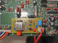
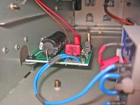
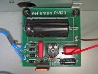
The best solution for me is to use the Cuno's PSU with a pre-regulation and a new transformator (i use a Velleman KIT ref : K1823). I think the problem was due to find a good alimentation line on the board of the VRDS. His PSU is very complex and there is a lot of trap to recuperate a goog line, specialy with the Cuno's PSU.
Concerning the most important : THE SOUND !
I don't notice a large improvement. Maybe high frequencies are more bright, but i think i'm too old to ear a significant difference.
Cordialement à tous.
After a lot of test, here is my last contribution to this topic :
The best solution for me is to use the Cuno's PSU with a pre-regulation and a new transformator (i use a Velleman KIT ref : K1823). I think the problem was due to find a good alimentation line on the board of the VRDS. His PSU is very complex and there is a lot of trap to recuperate a goog line, specialy with the Cuno's PSU.
Concerning the most important : THE SOUND !
I don't notice a large improvement. Maybe high frequencies are more bright, but i think i'm too old to ear a significant difference.
Cordialement à tous.
Attachments
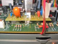
OPA -- you must have a nice "macro" lens on your camera -- the pictures are quite informative.
If you have to "trim" consider using a twisted-pair (CAT-5 wire is OK) a few centimeters will give you enough picorarads to shift the frequency a few hundred Hz.
Just from my ham radio days -- the next step would be to take the XO, box it up (with some spare PCB material) and temperature stabilize it -- you can use a resistor as the heating element and a diode as the temperature sensor, or a centigrade sensor from Nat Semi.
jack
Let if burn
Ah yes, that's my findings too, and also what I posted some pages before on this thread.
Anyway, when I first ordered my Tent clocks and used them them for the first time, I knew this was going to happen.
My Philips CD650 played horrible sounds on the first power-on.
I left it playing, and an hour later...

I have a good "vice" of reading the docs, so I knew this was going to happen.
This is on a doc Guido kindly sent me. At the end of the doc, "Customer satisfaction":
"Hi Guido,
Last Saturday I managed to squeeze that crystal oscillator inside my PhilipsCD471 ………………. It sounded terrible !!!!
Until an hour later ……now it is perfect J
I never realised that crystals need to break-in, I do not know, but now I got the result. Overall performance is cleaner, tight !"
jean-paul said:Leave it on for some days as the module needs some time to break in. It definitely performs sub-standard the first few hours of operation.
Ah yes, that's my findings too, and also what I posted some pages before on this thread.
Anyway, when I first ordered my Tent clocks and used them them for the first time, I knew this was going to happen.
My Philips CD650 played horrible sounds on the first power-on.
I left it playing, and an hour later...
I have a good "vice" of reading the docs, so I knew this was going to happen.
This is on a doc Guido kindly sent me. At the end of the doc, "Customer satisfaction":
"Hi Guido,
Last Saturday I managed to squeeze that crystal oscillator inside my PhilipsCD471 ………………. It sounded terrible !!!!
Until an hour later ……now it is perfect J
I never realised that crystals need to break-in, I do not know, but now I got the result. Overall performance is cleaner, tight !"
Re: Let if burn
The crystal is actually stabilizing its frequency with temperature -- that's why "ovenizing" the XO is a good idea.
carlosfm said:
I never realised that crystals need to break-in, I do not know, but now I got the result. Overall performance is cleaner, tight !"
The crystal is actually stabilizing its frequency with temperature -- that's why "ovenizing" the XO is a good idea.
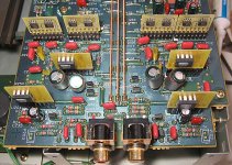
-------------------------------------------------------------------------------opa said:A last picture of a real improvement !
More improvement if you get rid of the coupling caps! Be very careful; my VRDS 20 did not have them and there is a dc offset adjust.
Hi,
I installed Lclock XO in my naim 3.5 few weeks ago, there was a positive improvement, than i added the double reg pcb with lm317/lt1086/lm329 for it. There was not so much difference and sometimes i am even thinking that it sounds worse, than WITHOUT reg pcb. Maybe some oscillation are appearing.
So, after reading some posts here about psu for xclock i decided to build just a clone of LCaudio xo or xo2 psu.
I searched the threads here and found those sentences from Lars Clausen:
---------------------------
It is not about the price per se, as you mention the regulator really cost nothing. On the other hand we have a very good regulator on boad the LClock XO and others. Before this regulator we want to have a dynamic power supply without feedback loops (like exist in usual regulators) as these loops have f corners that may in some cases affect the oscillator further down the regulator chain.
---------------------------
When you use the CD player's power supply, the ground potential for this power is taken from the CD player's ground.
When you use an extra power supply, the return path is kept to this power supply, so the CD player is connected to the clock signal only.
That gives the main performance difference of these two options.
---------------------------
---------------------------
Now i have some questions:
Unregulated psu design. I found some photos of the psu
http://www.tnt-audio.com/jpg/lclockxopsu.jpg
http://www.lcaudio.dk/com/hyperkit.jpg
There is just a small trafo, probably ERA 3.2 VA/12(?)Volts AC secondary, than a rectifier, two small caps and two 2200uF/25V
1. What is a secondary delivering, is it 12V AC -> 16.9DC or 9V AC ->12.7DC ?, or ?
2. Rectifier is made of schottkys, or normal diodes ?
3. Two small green caps - how they are connected ? Just bridging big caps, or ?
Maybe somebody just has a schematic. But i just want to make a clone of LCaudio psu and do not want to start another discussion regulated/unregulted etc
And a question about connecting the ps and xclock. Lars is writing about it, but it is still not so clear for me.
So - the clock will be connected with two wires (+ and ground) to the extra power supply. Than a clock has already ground connection to the extra psu, should it be also connected to the ground near the clock input (like now - red cable is giving the signal and black is ground close to the input signal), or there will be only + signal cable connecting clock with the main cd pcb ?
Cheers, sinski
little
sinski said:Hi,
I installed Lclock XO in my naim 3.5 few weeks ago, there was a positive improvement, than i added the double reg pcb with lm317/lt1086/lm329 for it. There was not so much difference and sometimes i am even thinking that it sounds worse, than WITHOUT reg pcb. Maybe some oscillation are appearing.
------------------------------------------------------------------------------
I am not surprised. The LT1086 is one NOISY regulator and I cannot understand why it is promoted in this forum by some. It is worth investing/building an ALW version of the Jung regulator. Search here!
It is ultra stable, ultra low noise and sounds good.

Hi,
Maybe one day i will try ALWSR also, i even ordered few pcbs from Andy. Andy is using one special low noise version of the sr in his 3.5, but he had to adapt it in some way. So i decided to just make a solution proposed by lcaudio, maybe somebody can answer my questions from the last post ...
Cheers, sinski
Hi,
So i did the simple clone(i think it is very close to it) of the LCaudio psu. It was one 3.2VA 9Volts Tranny, then one 0.01uF mkp across, than a small rectifier, than 2x2200uF/25Volts and again one 0.01uF MKP across. IMHO the sound improvement is really noticeable and this psu works much better than reg pcb with lm317t(lt1086/lm329. It looks like LCaudio knows what they are doing. Maybe my double reg was oscilating and creating a lot of jitter, i don't know.
Cheers, sinski
I have not a good drawing programm, but it simple - just a small ERA Trafo 3.2VA/9Volts AC, than a small mkp 0.01uF bridging secondaries, before the rectifier, than two 2200uF/25V bridged with 0.01uF and this is all.
Be aware that such a small trafo is delivering without load about 18Volts after Rectifier (not just 1.41x9V), and with connected lclock it is about 16V DC.
Look at the photos in my older posts.
http://www.tnt-audio.com/jpg/lclockxopsu.jpg
http://www.lcaudio.dk/com/hyperkit.jpg
Cheers, sinski
Be aware that such a small trafo is delivering without load about 18Volts after Rectifier (not just 1.41x9V), and with connected lclock it is about 16V DC.
Look at the photos in my older posts.
http://www.tnt-audio.com/jpg/lclockxopsu.jpg
http://www.lcaudio.dk/com/hyperkit.jpg
Cheers, sinski
- Status
- This old topic is closed. If you want to reopen this topic, contact a moderator using the "Report Post" button.
- Home
- Source & Line
- Digital Source
- LClock XO PSU