Hi all,
I have purchased an XO cristal and built a power supply for it. Building this thing into the CD6000 player is not as easy as I thought it would be. Recognising components is difficult (SMD) and also the schematic that everyone has lacks the part around the clock.
Question 1:
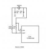
Are the two components next to the cristal the 2x 10p capacitors? I am asking because they look like resistors.
Question 2:
Which of the two capacitors is the inverter input? The one closest to the side of the cabinet ?
I appreciate all help !
Mark
I have purchased an XO cristal and built a power supply for it. Building this thing into the CD6000 player is not as easy as I thought it would be. Recognising components is difficult (SMD) and also the schematic that everyone has lacks the part around the clock.
Question 1:
Are the two components next to the cristal the 2x 10p capacitors? I am asking because they look like resistors.
Question 2:
Which of the two capacitors is the inverter input? The one closest to the side of the cabinet ?
I appreciate all help !
Mark
DutchMark said:Hi all,
I have purchased an XO cristal and built a power supply for it. Building this thing into the CD6000 player is not as easy as I thought it would be. Recognising components is difficult (SMD) and also the schematic that everyone has lacks the part around the clock.
Question 1:
Are the two components next to the cristal the 2x 10p capacitors? I am asking because they look like resistors.
Question 2:
Which of the two capacitors is the inverter input? The one closest to the side of the cabinet ?
I appreciate all help !
Mark
Mark
Yes, the caps lok similar to resistors. Try to follow the traces and you are sure about yourself
At my site you can download a document that helps finding out input / output.
http://www.tentlabs.com/Support/Mounting/XO2mounting.pdf
Otherwise you can identify the chip and look for the datasheet
succes
Guido
As I suggested recently in another thread about CD6000 I would divide the clock signal (with 74HCU04 for example) and separately feed both DAC chips + the signal processor where the clock is originally......
the thread
Rgds,
Ergo
the thread
Rgds,
Ergo
ergo said:As I suggested recently in another thread about CD6000 I would divide the clock signal (with 74HCU04 for example) and separately feed both DAC chips + the signal processor where the clock is originally......
the thread
Rgds,
Ergo
Yes, that helps, ofcourse
My own clocks can drive 3 gates, so need for extra buffer (which slightly increases jitter)
cheers
Hi Mark,DutchMark said:Hi all,
I have purchased an XO cristal and built a power supply for it. Mark
A XO is not a crystal but a complete crystal-oscillator.
It cannot be used in the KWAK-CLOCK.
You can download the schematic here:
http://www.diyaudio.com/forums/showthread.php?postid=199928#post199928

ergo said:One more try
Thanks Ergo,
Your print layout has been very helpfull. How did you get your hands on that !!!!
 If you have the full schematic, I would also be very interested.
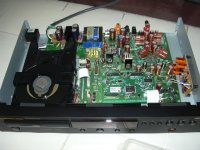
Anyway, I have perfrmed the modifications. I have built the XO osscilator with low noise independant power supply into the player. Since I had the player in bits on the table, I decided to go all the way and also remove the muting transistors and bridged the capacitors. I also scratched away the tracks leading to the other end of the board to provide signal to the head-phone amp.
The results: Mixed !!! The

Before I go on I should tell you what I have been using:
- Marantz CD6000
- DIY 300B single ended valve amp.
- Virgo II speakers (Dynamic Audio)
I can now touch intruments and singers as they can truely be pinpointed in space. This is great !!! It is like sound is completely surrounding me and coming out of walls. I suspect the clock to have provided the biggest contribution to this effect.
Also, when I play subtle vocals, the sound is great. Deffinition is extremely high.
I recently got my Virgo II speakers. Previously sound has been really civil when I used this set. In the high frequencies, sound was modest. Definition was ok, but high prequencies were not agressively present. This created a combination I could listen to for hours.
After the modefications high frequencies (5-10k) are much more prominently present. As a result sound has become more fatighing.
Does anyone recognize this effect or have suggestions. I am considering to place back the electrolitics in the signal pathway.
Regards,
Mark
Re: Elso !!! How Kwak-7 install to Marantz CD6000
Hi, remove both 10p caps and 1M resistor and crystal. Use crystal in KWAK-CLOCK. Connect output of KC to pin 36 XTIN. Don't forget to connect the ground of KC. Ground pads of 10p caps can be used to connect the ground lead.
Use raw digital supply for KC.
l_paitoon said:I'm not understand install Kwak-7 to Marantz CD6000
Hi, remove both 10p caps and 1M resistor and crystal. Use crystal in KWAK-CLOCK. Connect output of KC to pin 36 XTIN. Don't forget to connect the ground of KC. Ground pads of 10p caps can be used to connect the ground lead.
Use raw digital supply for KC.
DutchMark said:
Thanks Ergo,
Your print layout has been very helpfull. How did you get your hands on that !!!!
Anyway, I have perfrmed the modifications. I have built the XO osscilator with low noise independant power supply into the player. Since I had the player in bits on the table, I decided to go all the way and also remove the muting transistors and bridged the capacitors. I also scratched away the tracks leading to the other end of the board to provide signal to the head-phone amp.
The results: Mixed !!! The
Before I go on I should tell you what I have been using:
- Marantz CD6000
- DIY 300B single ended valve amp.
- Virgo II speakers (Dynamic Audio)
I can now touch intruments and singers as they can truely be pinpointed in space. This is great !!! It is like sound is completely surrounding me and coming out of walls. I suspect the clock to have provided the biggest contribution to this effect.
Also, when I play subtle vocals, the sound is great. Deffinition is extremely high.
I recently got my Virgo II speakers. Previously sound has been really civil when I used this set. In the high frequencies, sound was modest. Definition was ok, but high prequencies were not agressively present. This created a combination I could listen to for hours.
After the modefications high frequencies (5-10k) are much more prominently present. As a result sound has become more fatighing.
Does anyone recognize this effect or have suggestions. I am considering to place back the electrolitics in the signal pathway.
Regards,
Mark
Hi Mark
2 Notes
- What power supply did you use, and how low is that noise ?
- When improving your clock, the resolution increases. This may emphasise other system aspects, it is what I call the magnifying glass efect. Flies start looking scary when you watch them using such glass.
succes
The results: Mixed !!!
Before I go on I should tell you what I have been using:
- Marantz CD6000
- DIY 300B single ended valve amp.
- Virgo II speakers (Dynamic Audio)
CD6000 is very balanced and low noise design and sounds pretty good in original form. Installing an external clock oscillator is not an instant improvement. It is the oscillator power supply that needs (the most of) attention. It has to have very low noise level and spectrum. Low level of noise will give you sound free of fatigue, and different noise spectrum will COLOUR the sound. You should check the noise level at your oscillator power supply (could you maybe post the oscillator and power supply circuit diagrams and photos of installed clock oscillator in your CD player?).
Your system is very revealing (single ended 300B!!) and will immediately show everything you've been doing with your system - every little thing! This is in fact very good, because if you are keen to experiment (and do a lot of searching here on forums - it is full of great suggestions!), you may be able to discover what your CD player is capable of. The main problem and area you should improve is decreasing the noise in power supply rails.
Another thing; if your ground plane is noisy, decoupling is not going to work – capacitors won’t be able to decouple the power supply pins no matter how good they are, or how close to the IC pins they are installed. You’ll be wasting your time and money. Many people buy expensive external clock oscillators and analog stages / filters – and connect them to the EXISTING power supply rails – ouch!
Good luck,
Extreme_Boky
Hi Im making a low noise power supply for my CD6000 clock and Ive come across this post.
1./ should I use the same supply for the 74HCU04 or a separate supply.
2./ I cant find one of these locally, is it OK to use 74HC04 (not U variant) as they are easy to get. Im aware the U is for oscillator, but cant find one.
3./ can some one explain what the following means and what pins I need to use to get this thing going.
Key
V = VCC (+5V)
G = ground
H = logic 1 (VCC) - inputs at VCC for HC types;
3.5 V for HCT types
L = logic 0 (ground)
D = don’t care - either H or L but not switching
C = a 50 pF load to ground is allowed
O = an open pin; 50 pF to ground is allowed
P = input pulse (see illustration)
Q = half frequency pulse (see illustration)
R = 1kW pull-up resistor to an additional 5 V supply
other than the VCC supply
B = both R and C.
Im not sure hw this buffer works. I asume there should be one signal input pin for the clock signal(maybe one of the two P pins), and I need to use 3 of the outputs (pins C?) to connect to the two dacs and the reciever chip?
thanks Arthur
As I suggested recently in another thread about CD6000 I would divide the clock signal (with 74HCU04 for example) and separately feed both DAC chips + the signal processor where the clock is originally......
1./ should I use the same supply for the 74HCU04 or a separate supply.
2./ I cant find one of these locally, is it OK to use 74HC04 (not U variant) as they are easy to get. Im aware the U is for oscillator, but cant find one.
3./ can some one explain what the following means and what pins I need to use to get this thing going.
Key
V = VCC (+5V)
G = ground
H = logic 1 (VCC) - inputs at VCC for HC types;
3.5 V for HCT types
L = logic 0 (ground)
D = don’t care - either H or L but not switching
C = a 50 pF load to ground is allowed
O = an open pin; 50 pF to ground is allowed
P = input pulse (see illustration)
Q = half frequency pulse (see illustration)
R = 1kW pull-up resistor to an additional 5 V supply
other than the VCC supply
B = both R and C.
Im not sure hw this buffer works. I asume there should be one signal input pin for the clock signal(maybe one of the two P pins), and I need to use 3 of the outputs (pins C?) to connect to the two dacs and the reciever chip?
thanks Arthur
A better solution. See post 114/115.
http://www.diyaudio.com/forums/showthread.php?postid=275730#post275730
http://www.diyaudio.com/forums/showthread.php?postid=275730#post275730
Luke said:thanks rfbrw,
I have actually searched for something and saw that one, however there are no parts values. Do you know what they are?
I have some idea of the values I'd use but you best put in a call to the designer, Jocko. In the meantime http://cirrus.com/en/pubs/appNote/an33.pdf
- Status
- This old topic is closed. If you want to reopen this topic, contact a moderator using the "Report Post" button.
- Home
- Source & Line
- Digital Source
- CD6000 Clock upgrade practicallities