I have identified a design error, or a persistent manufacturing error, in Terratec's "24" bit 96kHz USB sound card.
The input is always polluted with a noise peak at around 10kHz, in addition to a sharp spurious spike at around 30 kHz. You can see the rising noise floor in the image, the spike I do not have pictures of online. This degrades the SNR to 71 dB or so, well below the 98 dB advertised by Terratec, and utterly unacceptable in a recording ADC.
These phenomena have been seen independently on several Phase 26s, in several countries, so it is not a solitary defect. Neither are these effects inherent to the AKM4586 codec used. On its own this device should be capable of a completely flat noise floor.
Reported it to Terratec, had a ticket issued, and got only silence ever since.
As Terratec are obviously not willing to fix this issue, I am on my own.
The ingress is probably related to the switching PS used to generate +5 and -5V from the USB bus power. Does anyone have a complete or partial schematic of the Phase 26, giving me some insight into the switcher?
Thx
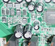
I spent a couple of hours reverse engineering the Phase 26 and
trying to fix its noise problems. I dump my findings here, it may be of use to other victims of TerraTec. Hell, it may even be of use to the 'engineers' TerraTec employ.
The chip labelled LTTS is an LT1945 switching regulator, generating
+5V and -5V from the raw USB power bus (4.8V with my Dell).
The +5V is used to feed all of the opamps and the AKM4586 codec, the -5V is
used on the opamps, and the USB 4.8V feeds all the rest of the logic.
The LTTS does not run at a fixed frequency, but rather uses feedback to 'push' packets of 350mA onto its output capacitors whenever the output voltage sags below a predetermined level. In other words, switching frequency is low when the load current is low, and vice versa. Switching can be influenced by either modifying the load (higher I, higher f), or by modifying the output capacitor(s) of the LTTS (higher C, lower f), or by the input voltage (higher V, lower f).
The +5V side, feeding opamps and codec, switches at around 40kHz. The much lower loaded -5V side switches at 10kHz in my case.
C101 is the input capacitor, 10uF. Increasing it to 1000uF does not change a thing, indicating that the noise ingress is through the post-LTTS supply lines, rather than induced by the 350mA current packets racing all over the PCB.
C102, 10uF, together with a nearby elcap of 220uF, is the -5V output cap. Increasing to 2200uF moves the 10kHz noise peak down to 500Hz and down in level, but the sound of that noise is rather ugly, like a helicopter. Clearly, switching noise should be made higher than 20kHz or even 40kHz, so that the ADC's AA filter can deal with it.
Reducing the -5V output cap is feasible, but requires total disassembly in order to remnove that 220uF cap, perhaps replacing it with 47uF.
I did not do that: adding 100R over C102, increasing the load with an additional 50mA, also did the trick, resulting in a noise floor at -117dB up to 5kHz, rising slowly to -110dB at 20kHz and higher. Before the mod my noise floor sounded like a highly-pitched hiss, with some light crackle below that, after the mod only the crackle was left. Dramatically better, but still a far cry from true 16 bit performance, let alone '24 bit'.
C103, 10uF, and a local 220uF, form the +5V output cap. Increasing these with another 220uF or maybe even more does not remove the 40kHz spike, but at least damps it with 15dB or so. However, with the -5V side fixed, nothing could be done to fix the +5V side. For that dismantling and changing the 220uF cap for something smaller might be required.
Attachments
While I'm at it ...
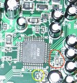
Increasing the value of the capacitor in the red circle flattens out the noise spectrum below 100 Hz. This capacitor serves as an AC ground for the ADC's input signal, both channels, so using a low-distortion component like Cerafine or Silmic might be worthwhile. I simply soldered a 22uF 10V ZA over the ceramic capacitor already present there.
Adding some capacitance to the little cap in the yellow circle lowers the overall noise floor with another 1 dB. This cap is the sole local decoupler for the AKMs analogue section, and it also feeds the ADC section's reference input node.
Attachments
The whole problem and solution is very interesting:
http://www.tnt-audio.com/clinica/regulators_noise1_e.html
http://www.tnt-audio.com/clinica/regulators_noise1_e.html
- Status
- This old topic is closed. If you want to reopen this topic, contact a moderator using the "Report Post" button.
- Home
- Source & Line
- Digital Source
- Terratec Phase 26 circuit diagram? Problems, no service!