Yay! Ive been wanting to make one for ages and have now finally completed the thing!
Basically lots of thanks go the MWP for the use of his DAC schematic as guidance, I had no idea whatsoever what was required to build a DAC before this. Anyway.
My version uses the DIR1703 SPDIF receiver coupled with a PCM1798 DAC chip. OPA627 perform the first pair of opamps after the DAC and then Analog devices AD797's for final shunt.
The IV stage has metal film 1% resis and high quality polystyrene caps.
The pin configuration for the 1798 is identical to the 94, if I can get hold of one from somewhere Ill see how much the better the superior chip sounds over the 98. I cant get samples of the 94, nor can I find anywhere to buy them from? As this is meant to be TI's flagship along with the PCM1792 you'd think they'd want then to be available to people.
Anyway now on to the good stuff, sorry no pics for the moment as the camera is not working currently with my PC (USB troubles), but appart from that it sounds great! no doubt this has something to do with my other post about grounding and all the negative comments I got from my old PCB made me redo it, much better. In comparison to my TEAC T1 dac it is better, which was the object of this exercise.
The bass is noticeably more tuneful and tighter, its very smooth sounding without any spit or harshness to it. The T1 was also very smooth too but not quite as smooth as this. The noise floor is obviously lower aswell and upon trasients or climax the sound does not seem to compress as much (compress is the wrong word). Absolute detail in single instuments or voices on their own is not that much different to the T1. The big difference is in micro detail, small sounds in the background are more easily apparent and some sounds that id not heard before are now present. All in all im very pleased with the results and am hoping it will only get better the more its used. The one thing im impressed with is how quiet it is, SILENT! wonderful.
One bit of experience (appart from learning how to make a DAC) ill take away from this is the use or SSOP to DIP converters, or just soldering SSOP in general. MAKE SURE THE PINS ARE SOLDERED DOWN!. I've had much heartache over it not working well because a couple of pins were not making contact properly.
I followed someone elses guide to soldering them which invoves soldermop or wick, this works really well, no more fretting over two pins soldered together.
Oh and those who say the DIR1703 data sheet is confusing, its not that bad you just need to get your head around it. OK I cant read those digital graphs but you dont really need to, to be able to make something of the chip.
Cheers Mat
Basically lots of thanks go the MWP for the use of his DAC schematic as guidance, I had no idea whatsoever what was required to build a DAC before this. Anyway.
My version uses the DIR1703 SPDIF receiver coupled with a PCM1798 DAC chip. OPA627 perform the first pair of opamps after the DAC and then Analog devices AD797's for final shunt.
The IV stage has metal film 1% resis and high quality polystyrene caps.
The pin configuration for the 1798 is identical to the 94, if I can get hold of one from somewhere Ill see how much the better the superior chip sounds over the 98. I cant get samples of the 94, nor can I find anywhere to buy them from?
As this is meant to be TI's flagship along with the PCM1792 you'd think they'd want then to be available to people.Anyway now on to the good stuff, sorry no pics for the moment as the camera is not working currently with my PC (USB troubles), but appart from that it sounds great! no doubt this has something to do with my other post about grounding and all the negative comments I got from my old PCB made me redo it, much better. In comparison to my TEAC T1 dac it is better, which was the object of this exercise.
The bass is noticeably more tuneful and tighter, its very smooth sounding without any spit or harshness to it. The T1 was also very smooth too but not quite as smooth as this. The noise floor is obviously lower aswell and upon trasients or climax the sound does not seem to compress as much (compress is the wrong word). Absolute detail in single instuments or voices on their own is not that much different to the T1. The big difference is in micro detail, small sounds in the background are more easily apparent and some sounds that id not heard before are now present. All in all im very pleased with the results and am hoping it will only get better the more its used. The one thing im impressed with is how quiet it is, SILENT! wonderful.
One bit of experience (appart from learning how to make a DAC) ill take away from this is the use or SSOP to DIP converters, or just soldering SSOP in general. MAKE SURE THE PINS ARE SOLDERED DOWN!. I've had much heartache over it not working well because a couple of pins were not making contact properly.
I followed someone elses guide to soldering them which invoves soldermop or wick, this works really well, no more fretting over two pins soldered together.
Oh and those who say the DIR1703 data sheet is confusing, its not that bad you just need to get your head around it. OK I cant read those digital graphs but you dont really need to, to be able to make something of the chip.
Cheers Mat
OK update, still no pics... they will come when I open up the DAC unit again when I get another PCM2902 shortly arriving, I fried the first one lol.
Anyway sound update. Having let this thing run in a little and let me acclimatise to it I now realise how much better it is then the T1 DAC. Everything is just better, no more needed, the trebble is better, the midrange is better and the bass is better. Nuff said unless you have a top DAC Id strongly advise building one around the PCM179x series of chips. Ive found a source for the PCM1794 so will order one and see if its any better then the 98.
If you like a very detailed smooth and brilliantly seperated sound youll love the PCM1798.
tobias_svensk said:I'm happy for you, when somthing you make by your own is sounding better then the things you buy your happy right?
Most definately happy
My speakers sound better then ones you buy, my amps sound better then the ones I had bought and now the DAC completes the chain. All my hifi is me made! appart from the digi source which is a computer, which I think ill leave to the pros lol.
Im comparing it against a TEAC T-D1 dac which is the parter for the VRDS T1 transport. I have both but now use neither.
The DAC is digitally filtered atleast I think it is.
Ofcourse I will post schematics and board layouts if people want them. The schematic is basically MWP's DIR1703 inplementation with TI's implementation of the PCM1798. Im not entirely sure how to get the board layout in a format thats accessable to everyone. I designed this on electronics workbench ultiboard, any ideas any1?
OK I decided to whip the lid off and took a few pics in the process.
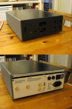
Right first pic the DAC clothed, I have not yet made a front panel so as you can just about see in the pic there are a few holes in the front. The case used to be a very high voltage PSU used for running gels which separate DNA. This was very handy as it had a filtered mains inlet with a switch and two fuses already mounted. I spray painted the lid black. The back panel hints to the origins of its original colour. Not very hifi!
Right first pic the DAC clothed, I have not yet made a front panel so as you can just about see in the pic there are a few holes in the front. The case used to be a very high voltage PSU used for running gels which separate DNA. This was very handy as it had a filtered mains inlet with a switch and two fuses already mounted. I spray painted the lid black. The back panel hints to the origins of its original colour. Not very hifi!
Attachments

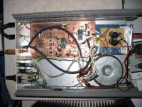
OK next up the top off! pretty much wysiwyg. Simple power supply to the right on vero board, regulators etc on main board. Beefyish 150VA traffo bought on ebay for £5 two 18v sec windings. The IV regs are LM317,337 arranged in the tracking preregulated fasion as described in the data sheet. The 5v reg is a LM340T 5v, all these run rather coolish so dont have any heatsinks. The 3.3v is an LM1086 which gets a bit warmer so I put a little heat sink I scavenged from a comp PSU on it. 4700uf of caps on each rail prior to this, very cheap nasty panasonics farnel had, still this thing sounds brilliant so im not worrying. Note the very short signal path!
Attachments
WoW you guys were quick lol, yes that certificate will be genuine however I dont think what ive cooked up inside would qualify
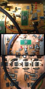
Last photo. This is really just a close up of the various bits, first of all is the DIR1703 with the PCM1798 lurking in the corner. You can see that there is an empty DIP socket to the bottom right, this is for a PCM2902 when I get a replacement, cooked the 1st one, had the USB wires wired back to front I dont think the chip liked it too much. Next is the PCM1798, here you can clearly see the sink on the reg. And then finally the IV stage, which has OPA627 first and then AD797. Here you can also see the polystyrene caps which are bloody huge in comparison to the polyester ones used elsewhere. The grey buses (ie box shape) near the opamps and 0.1uf polyes, the close caps to the four OPA627 are 8.2nf polystye you can see the difference there.
The original pics taken by the camera look a lot better then those but unfortunately are 600k each so you see the problem lol.
Last photo. This is really just a close up of the various bits, first of all is the DIR1703 with the PCM1798 lurking in the corner. You can see that there is an empty DIP socket to the bottom right, this is for a PCM2902 when I get a replacement, cooked the 1st one, had the USB wires wired back to front
I dont think the chip liked it too much. Next is the PCM1798, here you can clearly see the sink on the reg. And then finally the IV stage, which has OPA627 first and then AD797. Here you can also see the polystyrene caps which are bloody huge in comparison to the polyester ones used elsewhere. The grey buses (ie box shape) near the opamps and 0.1uf polyes, the close caps to the four OPA627 are 8.2nf polystye you can see the difference there.The original pics taken by the camera look a lot better then those but unfortunately are 600k each so you see the problem lol.
Attachments
Now for the slight nigle, appart from everything being great it has one small flaw. I get a small popping sound every now and again from the DAC, this is not really much of a problem but is a little annoying because it shouldnt be there. I have read somewhere else that another person had this problem and a man at TI I think said the DIR doesnt like jittery sources. Im using a Soundblaster live to drive this (it sounds MUCH better then a TEAC VRDS T1 so lets not argue why im driving this thing with crap like that haha) so it wouldnt be surprising if it was that.
Now MWP's schematic has a 47ohm resistor before the DIR on the SPDIF input, I had forgotten to add this originally and adding one made a big difference to how often it popped. Do you digi experts think making this bigger would solve the problem? Or do you think a SPDIF coupling transformer or whatever would be the ticket? If it is where do you get these things Ive only ever read about them, not seen.
Appart from the clicking brilliant.
Cheers Matt
MWP said:Is the popping being caused by interferance on the mains power supply?
As in, lights turning on/off, fridge compressor, etc?
Mine has this problem... never did have a good look at trying to fix it
Nope
its a digital thing I think.5th element said:My version uses the DIR1703 SPDIF receiver coupled with a PCM1798 DAC chip. OPA627 perform the first pair of opamps after the DAC and then Analog devices AD797's for final shunt.
Just want to remind you about the AD797,when it is used as a follower it should have a 100ohm resistor in the feedback path.Look in the data sheet.
I have used AD797 in my old modified cdp once,and I like it a lot,especially with a JFET current source(about 2mA) connected between output and negative rail....
MWP said:
You did the modifications to the circuit i mentioned on the web page?
Aye - R23 has been removed, and im assuming that the connection to ground is also broken from pin 5 of the TL77 once this has been done. Im meaning here that it once connected via R23 and it should remain unconnected once the resistor has been removed.
And then simply add another resistor between pins 5 and 7. of the same device.
Also if the BRSEL gubbins is not used (ie the hardware sample frequency select) should the DIR automatically sense the incoming sample frequency? Mine as it stands will only work with 48k, put a 44.1k in and it doesnt detect a signal?
- Status
- This old topic is closed. If you want to reopen this topic, contact a moderator using the "Report Post" button.
- Home
- Source & Line
- Digital Source
- My first DAC hurrah.