Hi averybody.
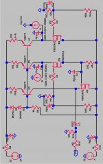
I made the D1 Output stage (see attached schematic), for my Teac VRDS8 player that uses 2 BB pcm 1702K per channel, and I have two problems that I can't resolve.
First one, the output level is less then 1 V with a 1KHz 0dB sinewave signal, and second problem, the signal out is highly distorted for strong input signals. Averything works fine if I pull down the digital level of the player of 10-15 dB, but tho output level becames really very low.
l have 32V rail, 0V on the source of the input fet and 16V on the drain.
I tryed to change the load resistor to 2K and 4K, and the bials current to 8.5 and 4.5 mA, but nothing is changed.
Could please samebody help me?
Attachments
Hi,
Had a quick look at your schematic, and I don't understand why your first Mosfet (M4) has no drain resistor...
Are your DAC (I output) balanced (One PCM per polarity ?) Where do you connect the PCM1702's outputs ?
I presume the two inputs are at the sources of M3 & M4. Right ? Feeding the I/V converter at the source of M4 won't give you any sound, and M3 will... Just add a drain resistor to M4, and duplicate the follower built around M1...
Why not build the D1 stage exactly like in the manual, and only pick up the + signal against GND for you single ended output? (at least if you have one inverted and one noninverted DAC output)
If you have only one noniverted DAC output build half an D1 stage. I don´t understand why you need that BC550 stuff at the sources, and why you build something like 3/4 of the D1 stage.
If you have only one noniverted DAC output build half an D1 stage. I don´t understand why you need that BC550 stuff at the sources, and why you build something like 3/4 of the D1 stage.
") Put it in, and let's try again. And with a low part count, you could have it balanced (for future use
Put it in, and let's try again. And with a low part count, you could have it balanced (for future use The input stage is neat. I like the fact that you pull constant current on the input stage. Other than that i agree with cheff there is no use for the left side of the input stage.
As for your problem have you checked the signal at the positive side of C1 with a scope, or DC voltage if you haven't got a scope.
The only thing i can think of is that you are close to one of the rails and clip with high input signal but you cannot be if you have 16v on the drain of the input fet.
As for your problem have you checked the signal at the positive side of C1 with a scope, or DC voltage if you haven't got a scope.
The only thing i can think of is that you are close to one of the rails and clip with high input signal but you cannot be if you have 16v on the drain of the input fet.
For Till.
The dac is balanced two pcm1702 per channel. The bc550 are just CCS, so I can also have a lower minus rail (also unregulated).
For Hjelm.
I don't have a scope (jet) but on the source of M1 I have 14V DC.
The problem seems to be a saturation of the dac not of the output stage. The data sheet of the 1702 just says that the output impedence in 1K and the output current +-1.2 mA.
I have completely isolated the output stage of the Teac so wouldn't be any interferences from it.
Aniway, I will try to apply the second follower and leave it unused.
Thanks to everybody
Ciao.
Thanks pro,
As the Fet should make the voltage across the resistors you substituted with CCS always constant, i can´t see whats the advantage of current sources. I only see more potentioal sources of problems...
Also a simple zehner regulator one Fet, 30 something volt zehner is less parts than those BC550s and easy to test for function without scope.
In case the problem comes from overdriving the DAC in some way (i suspect the voltage at the source is not properly hold constant at 0V because of thouse CCS) the most simple solution is to use resistors here as Nelson did. As you have balanced current output from Dacs, i would definitely build a full balanced D1 stage and for single ended output use only the + output side. In case voltage output is not enough what about higher resistor values, and in case current bias gets to small this way more voltage at the rails? In case voltage output gets to high, resistor between drains as Nelson volume control. For some reasons i do not understand yet i like the DAC with D1 stage i built better without volume control resistor between the + and - side....?
Tested both on my PCM63 version, and preferred the CCS... Just a matter of taste... One advantage is the much higher impedance.till said:i can´t see whats the advantage of current sources. I only see more potentioal sources of problems...
The CCS is not responsible here for voltage drifts. The gate voltage sets the source at 0V for a given current, and the CCS just adapts itself. Given the large voltage between CCS's collector and the emitter, the CCS is pretty insensitive to the real mosfet source voltage.(i suspect the voltage at the source is not properly hold constant at 0V because of thouse CCS)
As you have balanced current output from Dacs, i would definitely build a full balanced D1 stage and for single ended output use only the + output side.
Couldn't agree more

The 0V at input sources is quite stable.
I have already made an half D1 stage for the tda1541 and I had not any problems. See http://www.diyaudio.com/forums/showthread.php?s=&threadid=34191
Anyway I use regulated supply, and the use of 3 bc550 two diodes and a resistor for 3 CCs doesn't seems to be a lot of parts.
Ciao.
I have already made an half D1 stage for the tda1541 and I had not any problems. See http://www.diyaudio.com/forums/showthread.php?s=&threadid=34191
Anyway I use regulated supply, and the use of 3 bc550 two diodes and a resistor for 3 CCs doesn't seems to be a lot of parts.
Ciao.
I would use the one side of the stage and wait for the BZLS to build. (Guess what i use between amp and DAC)
In case we couple those drains i would expect something inbetween a single ended only one DAC signal and a balanced to single ended converters signal. As we add the two signals with the resistors, the differences will average to some degree dependend of resistor value. Unfortunately this will lower the voltage we made.
Another way would be to feed a differential pair like BZLS with the common gate FETs drains instead of feeding the pair of followers. This way we could make some voltage gain and a balanced to single ended converter in one step. The amount of FETs needed would stay the same. Because of the voltage gain of lets say 10 or so, we also could lower the resistor from drain to positive rail of common gate FETs and give them more bias.
Hy Everibody.
After a week of vacation, I found the problem of the distorsion.
I just confused the 33 hom resistor on the CCS of the follower, with a 33 Khom.
So, I have changed the the follower in common drain with a resistor on between drains, so, both dacs are working and I have a true balanced to unbalanced converter (Thanks Till).
The sound seems to be very impressive, a lot of presence of the instruments, with very dark space between them. High frequency haves a very fine grain.
I only have a problem. With some CD's I can hear some tics in the tweeters, but not in a trace change, just in the middle of the song, so it would not have to be the missing of the mute transistors, because on the trace change I don't have any tics.
Any idea about?
A question.
It is better to have an high gain in the first stage and low in the second, or viceversa?
Ciao.
Attachments
for the ticks, clicks, or whatever sounds: you don´t know on how many CDs i found clicks and so since i use the TD2001 horns.. Try to grab the CD on computer and look to the time you can hear the clicks with a wave editor and see if you find in in the PCM data.
For the gain: to me D1 sound best without resistor between the drains of M3/M4, so i would try to make only the gain you need in the second stage.
For the gain: to me D1 sound best without resistor between the drains of M3/M4, so i would try to make only the gain you need in the second stage.
Thanks Till. I'll try to take off the resistor on M3/M4.
For the ticks, i never heared them with the other 2 players that are both without mute. (A philips cd 582 NONOS and a Sony transformer coupled).
I have heared those thiks on HDCD CD's and 96/24 (Chesky)., never on CD-R or normal CD. Could he mean samething?
Ciao.
For the ticks, i never heared them with the other 2 players that are both without mute. (A philips cd 582 NONOS and a Sony transformer coupled).
I have heared those thiks on HDCD CD's and 96/24 (Chesky)., never on CD-R or normal CD. Could he mean samething?
Ciao.
- Status
- This old topic is closed. If you want to reopen this topic, contact a moderator using the "Report Post" button.
- Home
- Source & Line
- Digital Source
- D1 Output Stage Help needed.