If that's the "lower left" corner of the main PCB when looking facing the front, I think it is the "delay" circuit that controls the output-muting relay.
By memory I think this is a 100ohm resistor that controls the current charging one of those caps, that then through some transistor switches the relay. See post #12 above: it dissipates much more than the 1/4W it is apparently rated for.
_
I confirm!
The same thing happened to me!🙁
I replaced with a 0.6W.

Last edited:
Lately I have recovered an old CD2 from the attic; I wanted to remove the four TDA1541 but I didn't have the courage ...
All in all, it was quite clean inside and before identifying its problems I first thought about changing the old capacitors.
Indeed, after thirty years, several of them were at a loss.
Not having a service manual available, I thought of a simply conservative intervention.
The problem is that, in addition to the shabby one above, I found another burnt resistor (below are the related images): is the one in the middle of the three C546B. The tester tells me that it measures 12 Ohm but the external conditions do not allow to have certainties. And just in an attempt to better see the colors, unsoldering it I further wasted it!🙁
Can someone with good memory and experience on CD2 help me find out (or confirm) the resistor value?
Thanks.


I am looking for a CD2 Service manual - would be nice to PM me for the exchange - much appreciated1
I see that many are speaking here that they have it. So it seems that there is something?
I don't know what they have ... the CD player surely someone has it ...
Through the many photos that are on the net (and thanks to the examination of the circuit that saw the presence in the same sequence of a resistor of identical value) I managed to trace the correct value of the burnt resistor: 22 Ohm.
I have almost finished the extraordinary maintenance of the Cambridge CD2, only one LED is missing which I should soon recover from an old Philips CD player.
In the end, I also replaced 3/4 of the resistors with others of greater power: better be careful ...
When I finished and before closing ... I will make a summary!
🙂
CD2 Notes and Schematics
Seems like every now and then someone is looking for the never seen CD2 Schematic. I got the notes and schematic a few years ago and forgot I had them on an old laptop.
If the files don't show as attachments, PM me and I can send them to you.
Seems like every now and then someone is looking for the never seen CD2 Schematic. I got the notes and schematic a few years ago and forgot I had them on an old laptop.
If the files don't show as attachments, PM me and I can send them to you.
Buzz in sound output
Within this thread on the earliest pages, someone mentioned one of the common problems on the CD2, being noisy sound output, or even buzz.
Mine does this. So has there been an update on that?
Terence
Within this thread on the earliest pages, someone mentioned one of the common problems on the CD2, being noisy sound output, or even buzz.
Mine does this. So has there been an update on that?
Terence
Oh sorry folks. Just read that msg abt this issue.
It talks abt rebuilding psu. Sure, I was gonna build an outboard one separating each voltage. .
Terence
It talks abt rebuilding psu. Sure, I was gonna build an outboard one separating each voltage. .
Terence
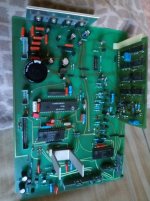
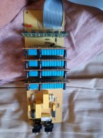
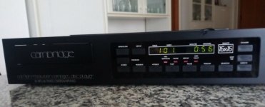
In the end, the Cambridge Audio CD2 has ... resurrected!
Thanks to Will and Bram for their help!
In the beginning, the CD player was practically a wreck ...
I replaced all the electrolytic capacitors, favoring conservative but intelligent maintenance.
Only for the lower values I preferred to replace them with plastic film capacitors.
Only in the laser control electronics did I put a modern organic polymer capacitor that I had.
I have recovered the led displays from old CD players.
The most boring job was to replace - by intuition - the resistors that could burn: the inadequacy of their value is known, given their aptitude to burn!
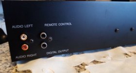
Lastly I replaced the old RCA connectors.
As soon as it was powered up, it turned on: after more than twenty years, it started working again!
And the listening is very good indeed!
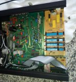
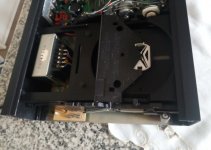


Last edited:
Very nice work! Happy to hear another one is up and running again.
What CD players did you use to harvest the working LED displays?
What CD players did you use to harvest the working LED displays?
Philips CD371 ... but there are many other suitable ones... but have you seen these?
https://www.digikey.co.uk/product-detail/en/lite-on-inc/LTM-8328PKR-04/160-1979-5-ND/3199164
https://www.digikey.co.uk/product-detail/en/lite-on-inc/LTM-8328PKR-04/160-1979-5-ND/3199164
Forza. As a CD2 owner myself it's great to see another going. Thanks for the replacement display info. If you ever care to take the lid off again you may wish to change the Op Amps, some caps around the DAC chips, the clock and PSU diodes. I also put heatsinks on the DAC chips (also put connector headers on the board for easier DAC board removal). As standard I cannot hear a difference between the CD2 and CD3, with the mods it's really noticeable. I did NOT convert mine to valve output. But you may find this interesting.
http://www.lampizator.eu/lampizator...3/Cambridge Audio CD3 CD player TDA1541A.html
http://www.lampizator.eu/lampizator...3/Cambridge Audio CD3 CD player TDA1541A.html
Thanks jotom750, it is always very interesting to have exchanges of experiences between audiophiles!
I honestly don't care about a tube output stage; but I gladly accept advice on everything else, starting with the opamps.
What did you replace the NE5534s with?
I honestly don't care about a tube output stage; but I gladly accept advice on everything else, starting with the opamps.
What did you replace the NE5534s with?
Hi Forza.
This is from one player, the OP Amps are OPA134's they work fine, I also have used LME 49710 the latter are a bit more detailed. I'm using the players with VFet amps so they are quite smooth, the 134's may be best for class AB amps. This one does not have heatsinks yet, but this machine has original air slots in the top where some do not so it keeps a bit cooler.
This is from one player, the OP Amps are OPA134's they work fine, I also have used LME 49710 the latter are a bit more detailed. I'm using the players with VFet amps so they are quite smooth, the 134's may be best for class AB amps. This one does not have heatsinks yet, but this machine has original air slots in the top where some do not so it keeps a bit cooler.
Attachments
- Home
- Source & Line
- Digital Source
- Cambridge Audio CD2
