Hi all
I have read some where in this forum about building passive low pass filter for DAC chip in CD player. The author recommends connecting the output of the DAC chip to ground via a resistor and a parallel capacitor. The entire original analog stage is bypassed. But I think he has a current output DAC chip.
I have a Marantz CD53MKII payer and I want to build a passive low lass filter for its NPC SM5872 DAC chip which has a 2v output. I have a couple of questions as follows:
1. Will the above method work with a voltage output Delta-Sigma DAC chip?
2. Will this DAC chip work with a 1st order filter?
3. Apart from the left and right output pins this chip also has negative left and right output pins. Should I connect the resistor and capacitor from positive pin to the negative pin or to ground?
4. Which value and type of resistor and capacitor do you recommend for this specific chip?
Thank you very much in advance for your help.
Hi quantran
First let me say, I'm no expert in this. But just hope to be of any assistance.
What you are trying to do is possible, but you have to have a look at the schematics first.
From what you are saying I conclude that your dac chip has symmetrical outputs, in most consumer players, this is then summed to single ended by means of a opamp. Then thereafter the filtering occurs with a second opamp (usually a dual opamp package for both).
I tried to look for your dac's spec sheet, but couldn't find one. Except this : http://www.tnt-audio.com/clinica/cd67.html
From that one it seems that you cannot just connect an RC filter immediately to the dacs output. (it just doesn't put out analog audio as such).
Sooo that means you'll have to get hold of some schematics first before you can do something. Try to get a service manual and post the relevant schematic around here, so somebody (else?) might have a better look at it.
BTW the values of the RC filter depend on the impedances before and after it, otherwise the -3dB points shifts.
HTH
Alien8,
Thank you for your advice. I have done some mods recommended by TNT-Audio including replacing the OPamp with the LM6172. There were significant improvements.
However once tried connect the DAC output directly I found the sound was much much better but the high frequency noise was also there. That's why I want to build a passive filter.
Here is the schematic:
Attachments
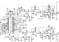
Well I was right about the summation, so unless you have a full symmetric system, you're one way or the other are going to have to sum them together. That means you need the summing opamp.
One thing you could try is to tap in at the output of the summing opamp and use the rc there, try 400 ohm + 10 nF to the output.
That *should* work as your pic says it is 0V offset.
The neat thing is you can leave the rest in as you try...
That should give you 6dB/oct filtering, probably the rest of your system and your ears will do the rest.
(those are things I learned from others on this forum)
Hello!
Look for the relevant DAC here: http://www.fortunecity.com/rivendell/xentar/1179/theory/vasfda/vasfda.html
Also keep in mind that the DAC output is balanced, and a lot of crap and noise is shut out by balancing the following stage - macthing the 10k and 27k resistors within 0,1% and using caps with tighter specs (like micas). You will be surprised and maybe forget the DAC direct out for a while. I've tried to find a simple balanced-in xformer for this purpose, but failed...anyone help?
Cheers,
t
Alien8 and Zombie,
Thanks a lot for your advice.
One guy on AA wrote:
"I bypass op-amp too and it's improvement too. SM5872 have 2V output and I used tube amp. I directly connect Pin 18 and 25 to RCA with just shunt R on each."
He also said that a coupling capacitor is needed.
It seems that he does not sum the + and -. Are there any problem with this approach?
Hmm
come to think of it, that might work. The difference between + & - terminals is the signal's 180 deg out of phase. I just wonder if the dac chip will be ok with asymmetric loading ?
you'll for sure need a coupling cap, your service manual says there's 1.4 V dc there, you'd rather get rid of that if you don't want to see smoke somewhere
Well, go ahead and try it I'd say !
(And please let us know the results )
come to think of it, that might work. The difference between + & - terminals is the signal's 180 deg out of phase. I just wonder if the dac chip will be ok with asymmetric loading ?
you'll for sure need a coupling cap, your service manual says there's 1.4 V dc there, you'd rather get rid of that if you don't want to see smoke somewhere
Well, go ahead and try it I'd say !
(And please let us know the results
)http://www.lundahl.se/catframe.html
The 1527XL have used according to people at audioasylum.com
Cost is about $60 x 2
Don't know about the 1,4V DC and if the xformer blocks it...
Cheers,
Tom
The 1527XL have used according to people at audioasylum.com
Cost is about $60 x 2
Don't know about the 1,4V DC and if the xformer blocks it...
Cheers,
Tom
The Dac’s outputs are not simply an inverted complementary pair; the modulation scheme used by the SM5872 (which uses commentary offset PWM modulation to gain an extra 0.5 bits resolution) requires outputs to be differentially summed to correctly reconstruct the audio signal. Therefore, you MUST use some form of differential summer to gain the full resolution and performance of the DAC.
John
John

quantran said:Hi John
What do you mean by "some form of differential summer"? Is there a way to do this using only passive parts?
Quan
you have to know the impedance -- but an RC filter will be of some help.
you might want to take a look at the FDNR (frequency dependent negative resistor) threads -- or the spec sheet for the AD713, or Burr-Brown (Texas Instruments) spec sheets on low distortion, low noise anti-aliasing filters.
The only way I know of to differentially sum with Passive components, is to use a transformer, but IMHO these are worst then opamps.
You could increase the order of the passive filter between the DAC outputs and the differential sum Opamp, there by reducing the “RF levels” seen by the Opamp input stage, then take the audio output directly from this Opamp - so there’s only one Opamp in the signal path.
I have always found the AD711 to be a well-behaved Opamp in the presents of RF.
See Cirrus Logic App Note AN48 for 2 Pole filter with differential input.
John
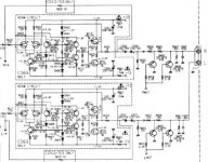
I would like to try to take the signal directly from diff. summing IC512 at pin 6 before R543 and leave out the LPF (IC513) and output buffer (IC514) completely in my Denon DCD3560.
But to avoid the worst HF I want to make a passive LowPassFilter. Can I do that just by replacing R544 with a cap? And which value should it be?
I plan to use OPA627 for IC511 and IC512. Any points of view on this project?
But to avoid the worst HF I want to make a passive LowPassFilter. Can I do that just by replacing R544 with a cap? And which value should it be?
I plan to use OPA627 for IC511 and IC512. Any points of view on this project?
Attachments
- Status
- This old topic is closed. If you want to reopen this topic, contact a moderator using the "Report Post" button.
- Home
- Source & Line
- Digital Source
- Passive filter for DAC?