As many people have built the dddac1543, I consequently received a lot of feedback on ways how to improve the design. Specially on the PCB lay out I had several.
Currently I am planning a version "mark II" where I will incorporate a number of ideas. As I do not want to rush into the new version, I like to ask the Forum inputs on 2 possible versions of the PCB design and values of the components find in the circuits below...
Next steps is to build a prototype with exactly the same components as my "reference" DAC at home, so a fair A-B comparison is possible between current and enhanced versions.
I am specially interested in feedback on the 2 versions of pcb design: One layer Starground or a 2 layer pcb with Groundplane.
Any other feedback is welcome, but please refrain from off-topic discussions about DAC chips for example for that we can open other topics
Looking forward to your feedback !
doede
Currently I am planning a version "mark II" where I will incorporate a number of ideas. As I do not want to rush into the new version, I like to ask the Forum inputs on 2 possible versions of the PCB design and values of the components find in the circuits below...
Next steps is to build a prototype with exactly the same components as my "reference" DAC at home, so a fair A-B comparison is possible between current and enhanced versions.
I am specially interested in feedback on the 2 versions of pcb design: One layer Starground or a 2 layer pcb with Groundplane.
Any other feedback is welcome, but please refrain from off-topic discussions about DAC chips for example
for that we can open other topics Looking forward to your feedback !
doede
Attachments
now you do this - and I JUST started soldering the thing together I have been collecting parts for since December
anyway - I'll send ample feedback
first of all, I think the PCB needs to be larger around the DAC tower to allow room for heat sinks that extend from the tower all around it.
Another thing - drop that battery checker section - who needs it? I read you can hook up a smart charger through a diode and never have to turn the thing off (or is that wrong? ever test it?)
I may just build the mk II if the mk I one turns out as sweet as everyone who has built it describes it.
more in a few days as I find a few resistors I fogot to order d'oh!
Peter
Re: Will there be one socket for 1543 or eight?
I still like the tower concept for its ease and short connections, but it is true that you need to make sure it cools well...
8 chips next to each other on a double layer board is ofcourse les of an issue...
Thanks for the feedback, I will keep this one in mind. Hope to get some more inputs on this subject (tower or loose chips on pcb)
doede
2A3SET said:To get easier placement of heat sink on top of each 1543.
Regards
I still like the tower concept for its ease and short connections, but it is true that you need to make sure it cools well...
8 chips next to each other on a double layer board is ofcourse les of an issue...
Thanks for the feedback, I will keep this one in mind. Hope to get some more inputs on this subject (tower or loose chips on pcb)
doede
pburke said:now you do this - and I JUST started soldering the thing together I have been collecting parts for since December
first of all, I think the PCB needs to be larger around the DAC tower to allow room for heat sinks that extend from the tower all around it.
Another thing - drop that battery checker section - who needs it? I read you can hook up a smart charger through a diode and never have to turn the thing off (or is that wrong? ever test it?)
I may just build the mk II if the mk I one turns out as sweet as everyone who has built it describes it.
more in a few days as I find a few resistors I fogot to order d'oh!
Peter
Hi Peter, no issue, this will not be ready for a longer time, I am sure you will enjoy the current version.... and by then you might want to do some experimenting again
If the results are not clearly better than the current version, I will not move on to a mk2 version any way. But lets wait and see ! I see this as an experiment to look for bounderies and what can be done....
Larger PCB, yes, some extra space could be good,
The battery checker is bought by more then half of dac-builders, so why not?
Konnichiwa,
Some thoughts. Make the DAC differential and modular.
Use small vertical daugther boards, 4 TDA1543 each with local PSU Reg and decoupling, re-clocking and buffering with the 4 Chips on one side and all the other logic on the other side, make the whole thing differential to start, so the basic version has per channel 2 Chips in Parallel/Differential.
You should then be able to use the modern nice copper RRAM cooler thingies to keep the chips running way cool and you can make the DAC highly scalable, all the way up to (say) 32 Chips (8 modules in parallel).
Also, the three dimensional layout with horizontal base PCB and vertical DAC modules can be used to keep all current loops really tight and short. I would design this also such that you can use a pair of batteries, one for the Receiver et al and one for the massive parallel differential DAC, which will with 32 Chips draw the better part of 2.5A!!!!
Lastly, a modest RAM buffer is not that hard to implement, why not go for it?
Sayonara
dddac said:Any other feedback is welcome, but please refrain from off-topic discussions about DAC chips for example
Some thoughts. Make the DAC differential and modular.
Use small vertical daugther boards, 4 TDA1543 each with local PSU Reg and decoupling, re-clocking and buffering with the 4 Chips on one side and all the other logic on the other side, make the whole thing differential to start, so the basic version has per channel 2 Chips in Parallel/Differential.
You should then be able to use the modern nice copper RRAM cooler thingies to keep the chips running way cool and you can make the DAC highly scalable, all the way up to (say) 32 Chips (8 modules in parallel).
Also, the three dimensional layout with horizontal base PCB and vertical DAC modules can be used to keep all current loops really tight and short. I would design this also such that you can use a pair of batteries, one for the Receiver et al and one for the massive parallel differential DAC, which will with 32 Chips draw the better part of 2.5A!!!!
Lastly, a modest RAM buffer is not that hard to implement, why not go for it?
Sayonara
Re-clocking ?
Hi
Your DAC looks nice!
One problem for me though. I don't see how it can work...
You are using a clock in the DAC that runs async from the clock in the transport. I.e. the DAC-clock will either be running faster or slower than the transport-clock.
How can this work ???
Is the single reason for using the TDA1543 that it doesn't require a master clock ?
Confused
/Urban
Re: Re-clocking ?
Hi Urban,
it works fine, no problem, this is not a new design, I am just looking for some improvement on pcb layout, grounding and power supply etc
The difference between the clocks is not audible. If you use 12 or 18Mhz, you get some problems, but as they are very close, it is no problem. Interesting result however, is the more open/wide/deep sound stage and better pinpoint....
It works with all DAC's. I had one version with PCM63 as well... worked perfectly
bc
doede
Urban said:Hi
Your DAC looks nice!
One problem for me though. I don't see how it can work...
You are using a clock in the DAC that runs async from the clock in the transport. I.e. the DAC-clock will either be running faster or slower than the transport-clock.
How can this work ???
Is the single reason for using the TDA1543 that it doesn't require a master clock ?
Confused
/Urban
Hi Urban,
it works fine, no problem, this is not a new design, I am just looking for some improvement on pcb layout, grounding and power supply etc
The difference between the clocks is not audible. If you use 12 or 18Mhz, you get some problems, but as they are very close, it is no problem. Interesting result however, is the more open/wide/deep sound stage and better pinpoint....
It works with all DAC's. I had one version with PCM63 as well... worked perfectly
bc
doede
Its an input !
Well, I sure learned something new today.
I looked up the CS8414 on Cirrus (didn't find any info on the 8412, but they are pin compatible)
The key to it all is that the SCK-pin (Serial Data Clock - pin11) can be defined as in INPUT to the CS8412. Have to read more on this.
I could possibly try this on my old DITB DAC. Hmm...
Thank's for explaining.
Cheers
/Urban
I personally like the DAC tower, I found mine quite easy to do once I figured out to use Arctic Silver adhesive to glue brass strips to the chips. As was mentioned the only problem was that there was not enough room for this, I had to move two components to the back of the board to have space for the strips coming out of the tower.
On the grounding, I would definately go with a ground plane approach, but I would break up the parts into different groups, each with its own regulator.
I would have the Tent clock on its own system to keep it as absolutely clean as possible. The current going into a CMOS chip is fairly low so there will not be much of a ground loop with it. BUT the inputs to the 1543 are TTL so they definately have siginicant current, especially when paralleling 8 of them. This means that its going to be tough to separate grounds, so a single ground plane is probably a good compromise here. I would put the Tent clock on 1 supply on its own, the divider chip and the reciever on the other and of course the DAC on its own high current supply.
Another major issue is bypassing caps. You need bypassing caps at each chip (well at LEAST one for the tower, if you can fit them in a couple along the tower helps). I added some .1 uf monolythic ceramic caps at each chip and it made a big improvement in sound. I would also probably go with at least 200uf (Panasonic FC is what I use) at the DACs in parallel with the .1 ceramic. The TL431s seem to work very well, but some bypass caps still help a lot.
Currently I'm implementing mine with three separate battery supplies using NiMH batteries, with a 7.2V NiMH for the DACs thus I bypassed the regulator altogether. (I tried 8.5 and could hear no difference)
Just one other little nit, the mounting holes were way too small. The only commonly available US screw that fits those holes is a 2/56, which only comes in very shorts sizes. Since I mounted some components on the bottom I needed to lift it up a bit above the base so I had to drill out the holes so I could use a 4/40 screw.
After running it for a couple weeks with the parts from the kit I switched the outputs over Vitamon Q caps and the sound is WAY good now.
Thanks for making this available, using the Tent clock really does help the basic concept.
John S.
Re: Re: DDDAC1543 mark II, asking the forum for Inputs
Son of a gun, it sounds like you are describing my current DAC project except I am using 32 PCM1704. There are four DACs per daughter board, arranged as differential pairs with local regulation and decoupling, etc, using 4-layer PCB.Kuei Yang Wang said:Use small vertical daugther boards, 4 TDA1543 each with local PSU Reg and decoupling, re-clocking and buffering with the 4 Chips on one side and all the other logic on the other side, make the whole thing differential to start, so the basic version has per channel 2 Chips in Parallel/Differential.
Doede,
Please allow me to break in with something that is a little off topic:
There is a DIY expo/trade show in Wetzlar in Germany in the middle of June. (http://www.jacmusic.com)
I understand that you live in Frankfurt, and that Wetzlar is not very far from Frankfurt. What is the best way to get from Frankfurt to Wetzlar?
Sorry for hi-jacking your topic guys
(Btw. I have built the 1543DAC myself on a Scott Nixon PCB.)
Just as John Swenson described it, I've put together my DAC towers (I am building two of these DACs at the same time) with copper strips and arctic silver glue (great stuff!). When I started I thought I would be able to bend the copper at the edges and then glue on a large heat sink, but the board doesn't seem to allow that. So ignore the shape of the fins here in the assembly stage. The glue settles in 5 mins, so you can put together a few pairs, then an hour later make 4-packs, and again an hour later you can build the 8 DAC tower and then leave it clamped to cure overnight. Soldering the finished tower is a breeze:
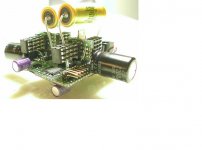
Now that I have most components on the board, I realized that the DAC had very little room in the direction of my heat fins. The small blackgate to the right of the tower location blocks the right side heat fins of the lower two chips, while the large heat sink for the LM1085 regulator prohibits a really long extension of the fins in that direction (ok, I should have bought a smaller heat sink but I believe in good cooling ;-)) That large capacitor on the top edge is a 47uF blackgate replacing the 20uF in the schematics at C10 - that's in response to the thread about the LM1085 startup noise. As you can see it's a rather big sucker and should also be moved away from the DAC area as well as the LM1085 heat sink. I had to bend it to the side to clear my heat sink.
Even the small pot to the left of the tower and the black resitor over there reduce the space for the heat sinking I had in mind initially. So what I'll be doing now is bending the fins up at a 45 degree angle and then use some more arctic silver glue to put copper fins at a 90 degree angle on the existing fins, enlarging the cooling surface by a few hundred percent. I'm not sure if that will be sufficient cooling without fans, but I'll try my best to avoid any fans. I have a few small fans that run pretty quietly at 5-6volts, but they still do make some noise I'd rather avoid.
In short - about 1" of clearance around the DAC tower location would be great to have.
and while I have your attention two quick questions: The "dot" on the Tent clock marks pin 1, right? I wasn't sure so I just stuck in into the socket for now. also, regarding the clock - there were two little chokes in the package -- where do I put them if anywhere? I plan to hard wire the clock without your Mode2/3 switch ('cause I haven't heard from anyone that not using the clock sounds better) - any reasons against doing so?
And I suppose that suggested 50ohm resistor on the output of the clock goes between pin 8 of the clock and pin 10 on the 74HC4040? I have one ready to go in there.
There's also that 1uF cap in the PCB instructions - I found it last night when putting parts on the PCB and since I had not ordered it (it's not in the schematics) I had to raid it from a broken SPDIF/Toslink converter box where I was lucky enough to find a few of these. Does this cap just lift the digital ground off the analog ground? I suppose I won't need a high quality cap there to make a difference. Actually, I am a little confused as to what to do with all these "ground" leads on the boards - do they simply all combine as I wire up the board? Would it make sense to put a copper plate under the PCB that is grounded, similar to your suggested ground plane, except spaced off the base of the PCB? Do I ground the chassis itself?
and if I was to bypass some pins on the DAC tower like John Swenson describes - what pins?
As you can tell - I have hardly a clue as to what I am putting together here. Take my questions as suggested changes to your manual/description. I'm sure I'll run into more issues. For example, I have a hunch my pots on the battery checker PCB are the wrong kind - I had to do some lead extension work to get them in there...
I'm sure I'll have some more questions as I get the DAC in there and start messing with the vref and other things I barely understand
An externally hosted image should be here but it was not working when we last tested it.
Now that I have most components on the board, I realized that the DAC had very little room in the direction of my heat fins. The small blackgate to the right of the tower location blocks the right side heat fins of the lower two chips, while the large heat sink for the LM1085 regulator prohibits a really long extension of the fins in that direction (ok, I should have bought a smaller heat sink but I believe in good cooling ;-)) That large capacitor on the top edge is a 47uF blackgate replacing the 20uF in the schematics at C10 - that's in response to the thread about the LM1085 startup noise. As you can see it's a rather big sucker and should also be moved away from the DAC area as well as the LM1085 heat sink. I had to bend it to the side to clear my heat sink.
Even the small pot to the left of the tower and the black resitor over there reduce the space for the heat sinking I had in mind initially. So what I'll be doing now is bending the fins up at a 45 degree angle and then use some more arctic silver glue to put copper fins at a 90 degree angle on the existing fins, enlarging the cooling surface by a few hundred percent. I'm not sure if that will be sufficient cooling without fans, but I'll try my best to avoid any fans. I have a few small fans that run pretty quietly at 5-6volts, but they still do make some noise I'd rather avoid.
In short - about 1" of clearance around the DAC tower location would be great to have.
An externally hosted image should be here but it was not working when we last tested it.
and while I have your attention two quick questions: The "dot" on the Tent clock marks pin 1, right? I wasn't sure so I just stuck in into the socket for now. also, regarding the clock - there were two little chokes in the package -- where do I put them if anywhere? I plan to hard wire the clock without your Mode2/3 switch ('cause I haven't heard from anyone that not using the clock sounds better) - any reasons against doing so?
And I suppose that suggested 50ohm resistor on the output of the clock goes between pin 8 of the clock and pin 10 on the 74HC4040? I have one ready to go in there.
There's also that 1uF cap in the PCB instructions - I found it last night when putting parts on the PCB and since I had not ordered it (it's not in the schematics) I had to raid it from a broken SPDIF/Toslink converter box where I was lucky enough to find a few of these. Does this cap just lift the digital ground off the analog ground? I suppose I won't need a high quality cap there to make a difference. Actually, I am a little confused as to what to do with all these "ground" leads on the boards - do they simply all combine as I wire up the board? Would it make sense to put a copper plate under the PCB that is grounded, similar to your suggested ground plane, except spaced off the base of the PCB? Do I ground the chassis itself?
An externally hosted image should be here but it was not working when we last tested it.
and if I was to bypass some pins on the DAC tower like John Swenson describes - what pins?
As you can tell - I have hardly a clue as to what I am putting together here. Take my questions as suggested changes to your manual/description. I'm sure I'll run into more issues. For example, I have a hunch my pots on the battery checker PCB are the wrong kind - I had to do some lead extension work to get them in there...
I'm sure I'll have some more questions as I get the DAC in there and start messing with the vref and other things I barely understand
My first 1543 DAC
My first TDA1543A DAC, just built few weeks ago.
8*chips for each channel, An EPLD for data re-arrangement to right/left channel for differential or single end. A small 90 degree daughter board carry 8chips total with 4 on each side to shorten the length of signal path and reduce overshoot or undershoot caused by signal reflection. I turn the chips tower 90 degree to prevent the toppest chip is cooked by the remaining chips !
and the heat disspation is better no matter the airflow is vertical or horizental way. How about the sound ? Amazingly good !!!
Thanks for you guys, you are the audio experts on this website contribute so much on 1543NOS so that we can learn from you and base on your experience to build our own equipments and don't have to start from scratch.
Attachments
- Status
- This old topic is closed. If you want to reopen this topic, contact a moderator using the "Report Post" button.
- Home
- Source & Line
- Digital Source
- DDDAC1543 mark II, asking the forum for Inputs