Re: This may work ........
Hi Andy,
I'm going to try your circuit this weekend.")
I'll try to deal with the ripple later, first thing is getting the 100V from the player's transformer.
Thank you very much for the help. I'll let you know about the results asap.
Jeroen
poynton said:Hi.
This may work...
But I have not tested it....
I don't know what the ripple would be like.
It also requires another cap across the output ?
Both halves are working as full wave doublers.
The output of 1 is sat on the output of the other.
I dont think it will go BANG !
Andy
Hi Andy,
I'm going to try your circuit this weekend.
I'll try to deal with the ripple later, first thing is getting the 100V from the player's transformer.
Thank you very much for the help. I'll let you know about the results asap.
Jeroen
A Better Idea ?
Hi.
I just looked through the many diagrams I have downloaded over the last fer months.
I came across this from M-F.
This is powered from a dual [ + / - ] supply .
I wondered if JeroenR could adapt the idea to his tube output stage?
Andy
Hi.
I just looked through the many diagrams I have downloaded over the last fer months.
I came across this from M-F.
This is powered from a dual [ + / - ] supply .
I wondered if JeroenR could adapt the idea to his tube output stage?
Andy
Attachments
Re: A Better Idea ?
Hi Andy,
Thanks for the suggestion.
The diagram looks like two voltage doublers with one of the supply woundings to ground. The cd104 transformer has a center earth tap so I can not connect one of the supply lines to earth. Perhaps there is a trick....
I saw the double transitor setup on a tuner-mod site. Doesn't that cause a voltage drop over the resitors?
Funny thing though. Add tubes and the sound improves? Well, if it sells who cares.
I must admitt that I looked a few times at your previous diagram but have difficulties understanding. Too little experience I'm afraid. I will redraw the diagram a few times, perhaps that helps.
Jeroen
poynton said:Hi.
I just looked through the many diagrams I have downloaded over the last fer months.
I came across this from M-F.
This is powered from a dual [ + / - ] supply .
I wondered if JeroenR could adapt the idea to his tube output stage?
Andy
Hi Andy,
Thanks for the suggestion.
The diagram looks like two voltage doublers with one of the supply woundings to ground. The cd104 transformer has a center earth tap so I can not connect one of the supply lines to earth. Perhaps there is a trick....
I saw the double transitor setup on a tuner-mod site. Doesn't that cause a voltage drop over the resitors?
Funny thing though. Add tubes and the sound improves? Well, if it sells who cares.
I must admitt that I looked a few times at your previous diagram but have difficulties understanding. Too little experience I'm afraid. I will redraw the diagram a few times, perhaps that helps.
Jeroen
Re: Re: A Better Idea ?
Hi.
The part I wanted you to look at was the way the supply lines were connected NOT the power supply itself.
It uses a supply the same as you originally did ie. +b, gnd, -b
You may be able to adapt you design in this way?
Andy
Ps did you post your tube design? If not, please post and I will have a look.
JeroenR said:
Hi Andy,
Thanks for the suggestion.
The diagram looks like two voltage doublers with one of the supply woundings to ground. The cd104 transformer has a center earth tap so I can not connect one of the supply lines to earth. Perhaps there is a trick....
Jeroen
Hi.
The part I wanted you to look at was the way the supply lines were connected NOT the power supply itself.
It uses a supply the same as you originally did ie. +b, gnd, -b
You may be able to adapt you design in this way?
Andy
Ps did you post your tube design? If not, please post and I will have a look.
Hi Andy,
Still looking at your last suggested diagram.
What happens if you connect two voltage doublers after the second diode. Will both branches be pushing it to a double voltage (again)? With the 104's center-earth it could then be symtrical around that centre tap and I have my earth.
Or is this complete cr..?
Jeroen
JeroenR said:Hi Andy,
Still looking at your last suggested diagram.
What happens if you connect two voltage doublers after the second diode. Will both branches be pushing it to a double voltage (again)? With the 104's center-earth it could then be symtrical around that centre tap and I have my earth.
Or is this complete cr..?
Jeroen
It is complete. should give around 100v+
andy
Re: Re: Re: A Better Idea ?
Do you mean to make the earth for the tube circuit floating? A virtual earth.
poynton said:
Hi.
The part I wanted you to look at was the way the supply lines were connected NOT the power supply itself.
It uses a supply the same as you originally did ie. +b, gnd, -b
You may be able to adapt you design in this way?
Andy
Ps did you post your tube design? If not, please post and I will have a look.
Do you mean to make the earth for the tube circuit floating? A virtual earth.
Re: Re: Re: Re: A Better Idea ?
A negative earth I mean.
JeroenR said:
Do you mean to make the earth for the tube circuit floating? A virtual earth.
A negative earth I mean.
Re: Re: Re: Re: Re: A Better Idea ?
Hi.
I think you are a little confused.
On the diagram below,
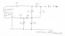
C1, C2, D1, D2 form a voltage doubler
C3, C4, D3, D4 form a second doubler
The voltage at the junction of D4, C4 is 25vAC doubled [ approx. 70v ]
The voltage from the other doubler will also be approx 70v.
Hence the voltage at the output will be approx. 140v [peak off load ]. This is measured between the existing ground and the junction of D2 and C2 [B+ in the diagram ].
The ground is the existing ground in the cd-player. It is not floating!
========================================
Refering now to the M-F circuit.
Ground is ground !!!!
The circuit has a B+ rail and a B- rail plus ground.
[ think op-amp power supply ]
=======================================
Please post your proposed tube circuit and I will try to explain with pictures.
Andy
JeroenR said:
A negative earth I mean.
Hi.
I think you are a little confused.
On the diagram below,
C1, C2, D1, D2 form a voltage doubler
C3, C4, D3, D4 form a second doubler
The voltage at the junction of D4, C4 is 25vAC doubled [ approx. 70v ]
The voltage from the other doubler will also be approx 70v.
Hence the voltage at the output will be approx. 140v [peak off load ]. This is measured between the existing ground and the junction of D2 and C2 [B+ in the diagram ].
The ground is the existing ground in the cd-player. It is not floating!
========================================
Refering now to the M-F circuit.
Ground is ground !!!!
The circuit has a B+ rail and a B- rail plus ground.
[ think op-amp power supply ]
=======================================
Please post your proposed tube circuit and I will try to explain with pictures.
Andy
Attachments
Re: Re: Re: Re: Re: Re: A Better Idea ?
Hi Andy,
Had some more time to look at the diagrams. I now see the errors in the first (wrong earth, shorting caps, that was silly). Attached are two diagrams, yours (V2) and the symetrical (V1). If I understand you correctly V1 will give 100V and V2 will give 140V. What will now give the most stable voltage (least ripple)? Also, in V2 the last cap C2 is connected to C4. Is this needed, could it be connected directly to earth?
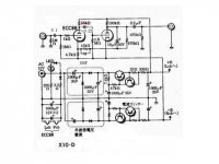
What I meant by the virtual earth; the tube circuit sees from plate to tube-earth let's say 40V because plate is at 20V and tube-earth is at -20V and of course the tube-earth is not connected to the real earth. (or am I understanding the X10 diagram incorrectly?)
In the meantime I'm going to build V2 as I have more trust in your design then in mine (understatement).
About the tube circuit, I posted the thorsten design somewhere in this thread. I would be a fool to think I could improve with my knowledge hence the copy. Also in this thread I suggested a value for the R-C between DAC and tube-stage. I will update the diagram this weekend with values and repost. The kathode resistors will be a (hopefully educated) guess though as I have trouble getting tube data for voltages around 50V.
So, off to buy some caps for the powersupply and in the meantime enjoy the jazz-festival this weekend.
I'll post the results later.
Thanks for the help/education so far,
Jeroen
poynton said:
Hi.
I think you are a little confused.
On the diagram below,
C1, C2, D1, D2 form a voltage doubler
C3, C4, D3, D4 form a second doubler
The voltage at the junction of D4, C4 is 25vAC doubled [ approx. 70v ]
The voltage from the other doubler will also be approx 70v.
Hence the voltage at the output will be approx. 140v [peak off load ]. This is measured between the existing ground and the junction of D2 and C2 [B+ in the diagram ].
The ground is the existing ground in the cd-player. It is not floating!
========================================
Refering now to the M-F circuit.
Ground is ground !!!!
The circuit has a B+ rail and a B- rail plus ground.
[ think op-amp power supply ]
=======================================
Please post your proposed tube circuit and I will try to explain with pictures.
Andy
Hi Andy,
Had some more time to look at the diagrams. I now see the errors in the first (wrong earth, shorting caps, that was silly). Attached are two diagrams, yours (V2) and the symetrical (V1). If I understand you correctly V1 will give 100V and V2 will give 140V. What will now give the most stable voltage (least ripple)? Also, in V2 the last cap C2 is connected to C4. Is this needed, could it be connected directly to earth?
What I meant by the virtual earth; the tube circuit sees from plate to tube-earth let's say 40V because plate is at 20V and tube-earth is at -20V and of course the tube-earth is not connected to the real earth. (or am I understanding the X10 diagram incorrectly?)
In the meantime I'm going to build V2 as I have more trust in your design then in mine (understatement).
About the tube circuit, I posted the thorsten design somewhere in this thread. I would be a fool to think I could improve with my knowledge hence the copy. Also in this thread I suggested a value for the R-C between DAC and tube-stage. I will update the diagram this weekend with values and repost. The kathode resistors will be a (hopefully educated) guess though as I have trouble getting tube data for voltages around 50V.
So, off to buy some caps for the powersupply and in the meantime enjoy the jazz-festival this weekend.
I'll post the results later.
Thanks for the help/education so far,
Jeroen
Attachments
weissi said:I would appreciate it if someone would fill my mailbox with a cd104 .pdf (service manual.....)
please send to " blomquist>remove this<@gmx.at "
THX alot.
should be on it's way but is 12Mb zipped.
Re: Re: This may work ........
Hi.
So what happened?
Andy
JeroenR said:
Hi Andy,
I'm going to try your circuit this weekend.
I'll try to deal with the ripple later, first thing is getting the 100V from the player's transformer.
Thank you very much for the help. I'll let you know about the results asap.
Jeroen
Hi.
So what happened?
Andy
Re: Re: Re: This may work ........
I spent a lot of time enjoying the sun and jazz-weekend. It was scorchio and the music great.
There was time to build the supply but no time for the test, photo and update of tube-diagram. I hope I can find time one of the evenings to post some results.
poynton said:
Hi.
So what happened?
Andy
I spent a lot of time enjoying the sun and jazz-weekend. It was scorchio and the music great.
There was time to build the supply but no time for the test, photo and update of tube-diagram. I hope I can find time one of the evenings to post some results.
jives11 said:
should be on it's way but is 12Mb zipped.
Thanks so much, but I'm afraid the file is only 8Mb and it seems it doesn't work. Nevertheless, I appreciate your help. regards, Markus
weissi said:
Thanks so much, but I'm afraid the file is only 8Mb and it seems it doesn't work. Nevertheless, I appreciate your help. regards, Markus
Hmmm, odd, it's a valid 12Mb PDF file in my googlemail sent folder. Are you sure you have downloaded the full attachment ? Most ISP's will not accept such a large attachment, but I didn't get a 'bounce message'.
anyway, no matter, I have sent a new mail with a different way to get the file
Re: Re: Re: This may work ........
Hi Andy,
It works.
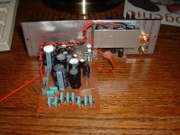
I measured 151.8V on the output.
The place of the supply looks a bit strange but there is the constant struggle for space inside the 104.
Saw today a CD104 offered on Marktplaats (Dutch EBay) for 100 EURO!!! I should be carefull with my 104, replacements are getting expensive I guess.
I will update the tube diagram in a few days and post.
Jeroen
poynton said:
Hi.
So what happened?
Andy
Hi Andy,
It works.
I measured 151.8V on the output.
The place of the supply looks a bit strange but there is the constant struggle for space inside the 104.
Saw today a CD104 offered on Marktplaats (Dutch EBay) for 100 EURO!!! I should be carefull with my 104, replacements are getting expensive I guess.
I will update the tube diagram in a few days and post.
Jeroen
Attachments
Re: Re: Re: Re: This may work ........
Hi.
Is that the 150v supply on the heatsink ??
looks good if it is .
Andy
JeroenR said:
Hi Andy,
It works.
I measured 151.8V on the output.
The place of the supply looks a bit strange but there is the constant struggle for space inside the 104.
Saw today a CD104 offered on Marktplaats (Dutch EBay) for 100 EURO!!! I should be carefull with my 104, replacements are getting expensive I guess.
I will update the tube diagram in a few days and post.
Jeroen
Hi.
Is that the 150v supply on the heatsink ??
looks good if it is .
Andy
Re: Re: Re: Re: Re: This may work ........
Yep, That's the one.
I used 47mF/160V caps as I was expecting 100V, not 150. Bit tight this way but at least it keeps the supply small. The red wire is the V-out. It is slightly boxed (alu) because it is close to outputs and the decoder/servo boards.
The decoder board is now empty where the opamps etc were. I hope to have just enough space for the tubes, caps and more caps...... and let's not forget the 6.3V supply.
poynton said:
Hi.
Is that the 150v supply on the heatsink ??
looks good if it is .
Andy
Yep, That's the one.
I used 47mF/160V caps as I was expecting 100V, not 150. Bit tight this way but at least it keeps the supply small. The red wire is the V-out. It is slightly boxed (alu) because it is close to outputs and the decoder/servo boards.
The decoder board is now empty where the opamps etc were. I hope to have just enough space for the tubes, caps and more caps...... and let's not forget the 6.3V supply.
- Home
- Source & Line
- Digital Source
- Philips CD104 tweaks