Hi,
Today is the first day of a CD104 modification adventure. I just received a CD104 and took it apart. Now I'm looking for a service manual with the decoder board part. Could somebody be so kind and send me a copy? My email address is rienk(dot)douma(at)gmail(dot)com.
Thank you!
Today is the first day of a CD104 modification adventure. I just received a CD104 and took it apart. Now I'm looking for a service manual with the decoder board part. Could somebody be so kind and send me a copy? My email address is rienk(dot)douma(at)gmail(dot)com.
Thank you!
Hi,
I have SM CD204 and CD304, completed. I'm interested in CD104. My e-mail is alekspinkfloyd@rambler.ru.
Thank you!
Aleksandr,
Sevastopol
I have SM CD204 and CD304, completed. I'm interested in CD104. My e-mail is alekspinkfloyd@rambler.ru.
Thank you!
Aleksandr,
Sevastopol
...
Also, I noticed there has been some work on this little player before. On the bottom side of the Servo PCB someone added a 1K resistor. See pic and artworkWhat's the purpose of this mod? Should I remove it?
Thanxs for all the info in this thread!!
Hi.
Great thread, I have yet to read the 50 pages in the middle of it!
Concerning this "1K resistor": It is not a resistor but a decoupling capacitor accross "Focus" driver transistors (6231-6232) supplys, I'd recommend leaving it in, in any case. (Although i have not yet done PS noise or "eye pattern" measurements with and without.)
I have two CD104 one servo board has the cap, the other does not, and it seems like a factory mod to me.
I do more repairs than mods, most of the time when I start on a CD104 or any other Philips of the same era I start by redoing all solders including SMD and without forgetting ground plane vias.
After only, if the player is still not working, start looking for "real faults".
Some are:
Spindle motor gone stiff, needs taking appart old grease cleaned off new grease back in.
Slack/Broken tray belt.
Bad electrolytics on CDM1 "U" shaped board.
Deformed/Sagging spring on focus lens.
Bad contacts in Mute/Pre-emphasis reed switches.
As for modding the most obvious to me would be getting a 16bit DAC in and adding some shielding between the Servo and DAC boards that are too close on the track sides.
Hi,
I'm another happy owner of good old Philips CD. Already done a lot of mods to my CD350:
-NOS
-changed all caps to Silmics & MUSE
-installed separate pcb with wima mkps for 2 TDA1540
-put some decent RCAs
-mains filter and socket
-replaced some SMD caps with wima mks
waiting for a separate clock module that will be attached to dedicated power supply.
meanwhile would like to install dedicated voltage regulators (LM317 i think) for 2 x TDA1540. Need to clarify few very simple things
-would it be enough to put 1.8VA transformer (9v, 200mA) to feed voltage regulator module based on Lm317 and TDA1540 (+5v only). Didn't find any consumption related data in TDA's specifications.
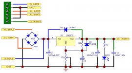
-according to TDA's specifications there should be 3 typical supply voltages +5, -5, -17. Pins 4,7 and 11 accordingly where 6th is the GND. So for +5 it's pretty clear - I need to connect DC output (pic in att) to pin 4 and GND to pin 6, right? Could anyone pls explaint me how to get -5V? Should I use LM317-LM337 scheme (att)?
I'm another happy owner of good old Philips CD. Already done a lot of mods to my CD350:
-NOS
-changed all caps to Silmics & MUSE
-installed separate pcb with wima mkps for 2 TDA1540
-put some decent RCAs
-mains filter and socket
-replaced some SMD caps with wima mks
waiting for a separate clock module that will be attached to dedicated power supply.
meanwhile would like to install dedicated voltage regulators (LM317 i think) for 2 x TDA1540. Need to clarify few very simple things
-would it be enough to put 1.8VA transformer (9v, 200mA) to feed voltage regulator module based on Lm317 and TDA1540 (+5v only). Didn't find any consumption related data in TDA's specifications.
-according to TDA's specifications there should be 3 typical supply voltages +5, -5, -17. Pins 4,7 and 11 accordingly where 6th is the GND. So for +5 it's pretty clear - I need to connect DC output (pic in att) to pin 4 and GND to pin 6, right? Could anyone pls explaint me how to get -5V? Should I use LM317-LM337 scheme (att)?
Attachments
thanks Andy,
now i got the point - I need some decent transformer 9v-0-9v or with 2x9v secondaries to get +ve and -ve.
btw is there any point installing two toroids, for instance, with dual secondaries for 2 TDA1540 or simply save some space and use only one, so there would be one LM317-LM337 module output of which would be connected to both TDAs +5,-5???
how do you think what is the minimum to supply TDA's + & - 5v? Some 5VA or should be higher? if two of them I guess should be 10VA already then...
now i got the point - I need some decent transformer 9v-0-9v or with 2x9v secondaries to get +ve and -ve.
btw is there any point installing two toroids, for instance, with dual secondaries for 2 TDA1540 or simply save some space and use only one, so there would be one LM317-LM337 module output of which would be connected to both TDAs +5,-5???
I would use a larger VA supply for the +5v and also for the -ve supply.
.
how do you think what is the minimum to supply TDA's + & - 5v? Some 5VA or should be higher? if two of them I guess should be 10VA already then...
Another option would be to use the standard power supply caps, improve their size and quality and get your unregulated DC from them.
I did so with my CD304 and my CD304 MKII – two additional LM317/337 for the +/-12V of the op-amps, two for the +/-5V of the TDAs and one -10V/-12V for the mostly analog -15V/-17V of the TDAs. For the -10V/-12V, I used the -5V as ground potential.
The results were fine and everything could be fitted inside of the CDPs.
For the CD350, I would go with a second transformer of about 30VA or bigger and dedicated smoothing caps as the standard supply is not as good as in the CDx04 versions and you have enough space to work with.
Apart from the mods you already did, I would suggest to get rid of the muting transistor and go direct from some better op-amps (OPA2134, OPA2604, LM4562, AD826) via a foil cap (2,2uF to 6,8uF, depending on your pre-amp) to the RCAs. Different op-amps can easily be heard while its harder with the difference between different foil caps.
Best regards,
StefanAC
cheers StefanAC!
a lot of mods still to be done and indeed there is a lot of space inside of CD350 Regarding LM317/337, did I get you right that I would need two sets of them (for +5, -5) feeding from one decent transformer? btw, any point using some good toroidal or could stay with a simple one?
Could you also pls advice me which capacity to use in LM317/337 smoothing part? I have good new BC 136 470uf caps, I was thinking to put 3-4pcs per rectifier or should be more?
I've read somewhere on the forum that OPA2132 is not so bad, much better than the original LM833 and NE5532. Which from the listed would you consider to be more aggressive and fast?
Frankly speaking didn't get about the foil cap, will use some search
thanks for your help!
a lot of mods still to be done and indeed there is a lot of space inside of CD350
Regarding LM317/337, did I get you right that I would need two sets of them (for +5, -5) feeding from one decent transformer? btw, any point using some good toroidal or could stay with a simple one?Could you also pls advice me which capacity to use in LM317/337 smoothing part? I have good new BC 136 470uf caps, I was thinking to put 3-4pcs per rectifier or should be more?
I've read somewhere on the forum that OPA2132 is not so bad, much better than the original LM833 and NE5532. Which from the listed would you consider to be more aggressive and fast?
Frankly speaking didn't get about the foil cap, will use some search
thanks for your help!
Concerning the transformer, I prefer El core types in a CDP. For the different voltages you need, some prefer to use a different winding for each voltage while others use one winding for all positive and a different one for all negative voltages. Others do it as it was done by Philips – one winding for the +/-5V and one winding for the +/-12V. So it is your choice as all methods have their advantages and disadvantages.
Using 3-4 470uF capacitors for smoothing sounds ok, I use the ones in the original power supply (now 3300uF/25V) with a MKP bypass. But I have read of people using 47000uF for each line with a 300VA transformer, so go as you like.
OPA2132 and OPA2134 are essentially the same – apart from the price. I tried both and there was no difference. The sound goes roughly into the NE5532 direction but improves in all areas. But depending on the rest of your equipment, the treble can be too much.
The OPA2604 is smoother but has to much bass with some set-ups.
The LM4562/LME47920 have better resolution and are one of my favorites.
Others I tested were AD825, THS4032, OP275, AD712, AD8620 and some more. But not all of them are plug and play and some need changes to the circuit or Brown Dog adapters.
At the moment, I use a pair of AD825 on Brown Dog adapters. If you get rid of the filter stages, an AD825 for I/U and a BUF634 as buffer should be great.
In the end, you should try to test as many different op-amp as you can get your hands on. Borrow them from friends; buy them as most are rather inexpensive. From my experience, they make the largest difference from any single component you can change in your CDP.
Best regards,
StefanAC
Last edited:
Cheers StefanAC,
I would definitely go for LM4562 and AD826, too many positive opinions they got here.
thanks for helping again! Could you also pls advice me on the following upgrades:
- replace ps diodes with Schottky (which ones would be better - 1N5822 or 1N5819 or some others). Also I suppose it's better to use them for dedicated power supplies for TDAs and opams.
- any point replacing chip caps under the diodes with some decent wima mks 0.047uf?
- disconnecting headphone circuit - removing NJM4560D, am I right?
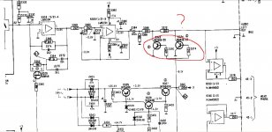
- removing chip muting transistors in CD350. Attached the picture where I marked them. Should I simply remove them and that's it?
I would definitely go for LM4562 and AD826, too many positive opinions they got here.
thanks for helping again! Could you also pls advice me on the following upgrades:
- replace ps diodes with Schottky (which ones would be better - 1N5822 or 1N5819 or some others). Also I suppose it's better to use them for dedicated power supplies for TDAs and opams.
- any point replacing chip caps under the diodes with some decent wima mks 0.047uf?
- disconnecting headphone circuit - removing NJM4560D, am I right?
- removing chip muting transistors in CD350. Attached the picture where I marked them. Should I simply remove them and that's it?
Attachments
Last edited:
The choice of Schottkys is not so important, I think. I prefer 11DQ10, but the differences are rather small compared to other mods.
The decoupling caps under the TDA1540 should never ever be replaced with caps of only one size! For correct sizes, consult the TDA1540 datasheet – the sizes mentioned there work best. For production simplification, Philips used only the lowest number of different caps sizes as possible. With the TDA1541, they even used a single size – which isn’t correct.
But I would stay with the SMD ceramic caps as this kind of cap is rather good for high frequency functions.
Disconnecting the headphone unit is good as well, it lessens the demand on the +/-12V power line.
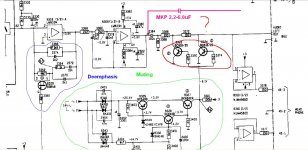
For the same reason, I would completely remove the muting circuit – especially the circuit that supplies the muting transistors with power. That would be the circuit in the green circle.
Furthermore, I would remove the de-emphasis as well – that’s the blue circle. And remove 2364 and get the analog signal directly to the RCAs by a MKP cap.
Best regards,
StefanAC
The decoupling caps under the TDA1540 should never ever be replaced with caps of only one size! For correct sizes, consult the TDA1540 datasheet – the sizes mentioned there work best. For production simplification, Philips used only the lowest number of different caps sizes as possible. With the TDA1541, they even used a single size – which isn’t correct.
But I would stay with the SMD ceramic caps as this kind of cap is rather good for high frequency functions.
Disconnecting the headphone unit is good as well, it lessens the demand on the +/-12V power line.
For the same reason, I would completely remove the muting circuit – especially the circuit that supplies the muting transistors with power. That would be the circuit in the green circle.
Furthermore, I would remove the de-emphasis as well – that’s the blue circle. And remove 2364 and get the analog signal directly to the RCAs by a MKP cap.
Best regards,
StefanAC
cheers StefanAC,
i very appreciate your help but as a newbie having quite limited practice and knowledge would like to ask you pls to clarify few things more.
if I place a cap after opamp do I need to remove red circle along with resistors (3370,3374) and res 3366, 3372. You wrote to send the analog signal after opamp directly to RCA, so just to confirm that all the red circle and few res above should be removed.
Regarding foil MKPs, what from the list would you choose:
-Wima MKP
-Mundorf Mcap
-MKP AudioPhiler
-Aluminum Foil mkp
as to the pre-amp I have Restek amp with quite basic preamp section (opamp buffer and two opamp gain stages. BB2604 is used). I guess 4,7uf would be fine?
i very appreciate your help
but as a newbie having quite limited practice and knowledge would like to ask you pls to clarify few things more.if I place a cap after opamp do I need to remove red circle along with resistors (3370,3374) and res 3366, 3372. You wrote to send the analog signal after opamp directly to RCA, so just to confirm that all the red circle and few res above should be removed.
Regarding foil MKPs, what from the list would you choose:
-Wima MKP
-Mundorf Mcap
-MKP AudioPhiler
-Aluminum Foil mkp
as to the pre-amp I have Restek amp with quite basic preamp section (opamp buffer and two opamp gain stages. BB2604 is used). I guess 4,7uf would be fine?
You can remove the resistors or leave them as long as you take the signal right after the opamp.
The first two MKPs I have used with good results, about the second two I don`t know anything. I prefer the Wimas or tin foil caps like Mundorf ZN. But the aluminium foil cap sounds like a good choice as well.
The size of the caps must be calculated with regard to the input impedance of the preamp. Just google the net for the maths.
For the de-emphasis it is best to remove everything. BUT I made a mistake in the drawing - don´t remove res 3356 and cap 2374. These are for the I/U conversion!
In general, I usually remove through hole parts while I leave SMD parts on the board - if they don´t matter. But that is just my opinion.
And as a newbie, I would advise you to read this thread completely and others concerning similar topics as they will give you a good insight in what you are about to do.
Best regards,
StefanAC
- Home
- Source & Line
- Digital Source
- Philips CD104 tweaks