I am lost. Desoldered, put metal threads through the holes, resoldered the griplets. The CD keeps on spinning counterclockwise and does not recognize any CD. What should I do next?
Regards
Truong
Measure all the rails to check they are correct. Using a scope to do this is far better than a DVM because you can see any problems with noise/ripple. If the disc is spinning backwards then check with a scope to make sure all the clock signals around the servo and system control are present and correct.
CD 104 Sensus
- double mono
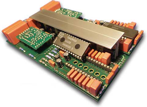
- 2 TDA1541A Converter with 4 channels
- mathematically correct connection of the DAC internal shift register
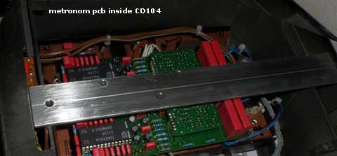
- dual channel synchronized shiftregister clock / Metronome
- 12 independent and separate channel voltage stabilization / Mono Power
- discrete output stages without chip operational amplifier / hybrid output
- 4 times DC servo without coupling capacitors in the signalpath
- 4 separate vibration-isolated module boards for converters and hybrid output
- continuous "Through Hole Technology" THT without SMD components
- selected premium components with tight tolerances
- thermally optimized layout with short signal paths
- fully remote control
- double mono
- 2 TDA1541A Converter with 4 channels
- mathematically correct connection of the DAC internal shift register
- dual channel synchronized shiftregister clock / Metronome
- 12 independent and separate channel voltage stabilization / Mono Power
- discrete output stages without chip operational amplifier / hybrid output
- 4 times DC servo without coupling capacitors in the signalpath
- 4 separate vibration-isolated module boards for converters and hybrid output
- continuous "Through Hole Technology" THT without SMD components
- selected premium components with tight tolerances
- thermally optimized layout with short signal paths
- fully remote control
DIGITAL OUT SPIDIF for 104, 204, 304?
Wow! That mod looks great!!!
Well done!
I am impressed!
A question to all here: Has anybody worked on a project to add a digital/spidif out on CD104 or 204 or 304 MKI in order to use it as a transport only and with an external DAC?
Please share your experience/ideas/projects/guidance if you have.
Thanks in advance to all replies!
Best regards,
Thank you Radko!
You want to build a spdif in an cdp with simultaneous data format?
It seems there are different ways.
1. You fetch a chip like altera max2 and code a data converting.
If you have experience in this, you had not asked. So i promise you need month to do like this.
2. you fethc a decoder board of a 304MKII and drive it paralel to the existing 14 Bit board. this seems mutch more easyer.
But why not take direct an MKII.
In my eyes that all makes no sense. Spdif is worse. you can build the best dac inside the 104,204,304 like the metronom. The best external dac will sound with spdif worse.
SPIDIF and DACs
Hi nanocamp,
Thanks for the message. The problem is that I am not familiar with the chip you mentioned. I will have a look into this thoygh.
Yes, you are right, if I had an MKII parallel board, or an MKII itself, it would make no good sense.
True, SPIDIF does sound worse, but still the Philips can make a great transport.
One other thing: Have you got extra set of boards from your project and do you sell them? I am curious to see how a 104 or 204 would sound with your mod project with two 1541s
Best regards,
Radko
Yes, you are right. The CDM1 is a good transport. But not with SPDIF and not with I2S! The DAC has to come in the CDP ore the CDM1 has to come in the external DAC. Same result, just a question wich case you like more.
There are only 8 boards now. They are allready soldered for build in CDP. No single sell this time.
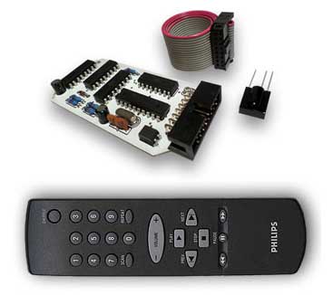
But maybe later. After a long summer break without beeing at home, i build another series. Then there is also a switching board with some relais (no Chip) to choose the source (CDP ore USB asynchronous). The layout is ready i will check it next weeks. The remote receiver has already the implement for the switch.
The remote receiver is available right now. If there are interests, i will make some mathematics about postage and price for DIY offer.
There are only 8 boards now. They are allready soldered for build in CDP. No single sell this time.
But maybe later. After a long summer break without beeing at home, i build another series. Then there is also a switching board with some relais (no Chip) to choose the source (CDP ore USB asynchronous). The layout is ready i will check it next weeks. The remote receiver has already the implement for the switch.
The remote receiver is available right now. If there are interests, i will make some mathematics about postage and price for DIY offer.
Another faulty CD-104
Hello everyone!
Let me wish you Happy New Year before I will ask you for help")
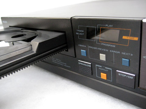
I am trying to fix my silver CD-104/30 player which does not spin the disc and signals the error every time I push the [PLAY] button.
Here is what I managed to check so far:
- the unit successfully enters service loop A (numbers counting up on the display) however it does not spin the disc (?)
- the spindle motor is ok since it runs nicely when injected with DC voltage
- the laser head moves up and down trying to find focus and I can see the red light through the lens
- the unit came through "griplet cure" procedure and most of the electrolytic capacitors were replaced
I followed Mike Leach tips regarding the laser unit and I found that there is no waveform on pin 14 (FCO) of IC6202 - pin 14 is constantly HIGH (however there are waveforms on pins 13 (FC1) and 12 (FC2)). Mike says that absence of this waveform will affect the focusing - the objective lens will rise only very slightly (I have no idea if the lens in my unit moves slightly or normally...). The absence of this waveform will also stop the turntable rotating, which is part of service loop A.
The FCO line (focus control ON - pin 14) should be 5V in the stop mode and 0V in play or TOC. And this is the part which I do not understand - my unit always gives 5V on pin 14 of IC6202 (FCO) - but maybe that is how it should be since it does not enter play or TOC modes and it permanently stays in stop mode. But this is in contrary to the statement that absence of this waveform will affect the movement range of the lens, isn't it? Anyone can guide me here? Please...
Hello everyone!
Let me wish you Happy New Year before I will ask you for help
I am trying to fix my silver CD-104/30 player which does not spin the disc and signals the error every time I push the [PLAY] button.
Here is what I managed to check so far:
- the unit successfully enters service loop A (numbers counting up on the display) however it does not spin the disc (?)
- the spindle motor is ok since it runs nicely when injected with DC voltage
- the laser head moves up and down trying to find focus and I can see the red light through the lens
- the unit came through "griplet cure" procedure and most of the electrolytic capacitors were replaced
I followed Mike Leach tips regarding the laser unit and I found that there is no waveform on pin 14 (FCO) of IC6202 - pin 14 is constantly HIGH (however there are waveforms on pins 13 (FC1) and 12 (FC2)). Mike says that absence of this waveform will affect the focusing - the objective lens will rise only very slightly (I have no idea if the lens in my unit moves slightly or normally...). The absence of this waveform will also stop the turntable rotating, which is part of service loop A.
The FCO line (focus control ON - pin 14) should be 5V in the stop mode and 0V in play or TOC. And this is the part which I do not understand - my unit always gives 5V on pin 14 of IC6202 (FCO) - but maybe that is how it should be since it does not enter play or TOC modes and it permanently stays in stop mode. But this is in contrary to the statement that absence of this waveform will affect the movement range of the lens, isn't it? Anyone can guide me here? Please...
CD 104 / 60 unknown conector in Decoder PCB
Hello Forum,
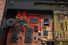
I am currently modding my CD 104 and am working right now on the decoder board.
In my service manual the connector marked in the image is not shown.
I found out that it has the line out on Pins 3 to 6, but I dont know what the first two Pins are for.
Maybe someone knows about them or can email me a service manual in better quality.
Thanks in advance
mabu
Hello Forum,
I am currently modding my CD 104 and am working right now on the decoder board.
In my service manual the connector marked in the image is not shown.
I found out that it has the line out on Pins 3 to 6, but I dont know what the first two Pins are for.
Maybe someone knows about them or can email me a service manual in better quality.
Thanks in advance
mabu
Attachments
Just a slight thread revival.
I have a grey CD104 with a pair TDA1540D's and after working well for the year or so of my ownership the left channel stopped working! I can hear output if I alter the amp's balance and turn the volume up but is that the channel or a little crosstalk from the other channel?
I've socketed the NE5532's to aid with doing an op-amp swap and did a simple swap to see if that was the cause of the channel dropout (it wasn't).
Whilst diagnosing the problem (unsuccessfully) I recorded the following voltages from the pair of op-amp
Right
1 3.6
2
3
4 -11
5 3.6
6 3.6
7 3.6
8 11
Left
1 3.6
2
3
4 -11
5 2.6
6 -10
7 -10
8 11
So from this 'simple' analysis I can see that one half of the op-amp is working (the I/V stage) but I'm getting nothing. At this point I made the decision to bypass the reed switches (no change) then decided that see if I could get an output from output of the first stage of the op-amp (before the capacitor) using a 1uf MKP1836. At this point I had output!
Any suggestions as to what could be the problem? I've currently got a pair of 10uf Clarity Caps in place bypassing both channels final op-amp stage whilst I find a solution to this issue.
Weird. You say you've ruled out the OP-Amps? It points to the Op Amp being faulty though with those Volt readings.
Maybe C2571 is going leaky? 2.6V across it instead of 3.4V. Would that cause the Op Amp to output full negative supply?
But then you say you've bypassed the final stage with a Cap, taken from across C2571 I assume, or is it from Pin 1? Still, with a leaky C2571 I would have thought there'd be some distortion audible?
Strange! I'll have another think!
CD104 no ouput on one channel
A few years ago I got one of these players with an identical problem.
In my case the culprit was the output capacitor (Philips ref 2573 or 2608) 22uF located just before the KILL switches (reed relais)
I took both out and measured them: One was a little under 10uF and the other only 200 or 300nF (don't remember exactly)
I replaced these and the problem was solved.
Afterwards I checked most of the lytics and found a few other out of spec and replaced these as well.
The player is working fine since.
I hope this helps.
Without looking into it too deeply I would guess that the OP Amp provides some Analogue Filtering to 'get rid' of the 'unwanted' 44.1kHz content that is 'on top of' the Music. Put the circuit into 'SPICE' or similar software and see what the Frequency Response curve shows.
The Capacitor Value along with R3579/3580/3581 and C2575 (just talking about the LHC only here) will also be doing the same. You are creating a CR Filter Network
https://en.wikipedia.org/wiki/RC_circuit
There are people who will say that without this filtering you'll fry your Tweeters/Amp but I have yet to come across anyone who this has happened to. I run my DAC with only an Analogue Filter operating around the 100kHz mark and have no problems whatsoever and the sound IMO is much improved for this. But that's a whole other discussion!!
Without looking into it too deeply I would guess that the OP Amp provides some Analogue Filtering to 'get rid' of the 'unwanted' 44.1kHz content that is 'on top of' the Music. Put the circuit into 'SPICE' or similar software and see what the Frequency Response curve shows.
The Capacitor Value along with R3579/3580/3581 and C2575 (just talking about the LHC only here) will also be doing the same. You are creating a CR Filter Network
https://en.wikipedia.org/wiki/RC_circuit
There are people who will say that without this filtering you'll fry your Tweeters/Amp but I have yet to come across anyone who this has happened to. I run my DAC with only an Analogue Filter operating around the 100kHz mark and have no problems whatsoever and the sound IMO is much improved for this. But that's a whole other discussion!!
Thank you for that big memory jog!
I'm renovating my CD104 mk1 at the moment and despite the transport side working fine (have TOC, all functions, plays smoothly, etc), can't seem to figure out what's causing intermittent audio out. Randomly the audio appears and sounds good, but gradually gets more distorted until it becomes silent.
Have checked all rails which are fine, pin volts against Philips spec, also fine, replaced all caps on the decoder + PSU boards, re-soldered everything including fixing griplets on decoder and servo boards, replaced -18v regulator, checked mute signals, bridged mute relay with wire and continuity tested the servo/decoder interconnection leads. Intermittent audio fault remains
I've traced the digital path as recommended in Mike Leach's servicing guide and all seems well until pin 22 of the DACs (i.e. analogue out). If there wasn't intermittent good sound on both channels, i'd assume they were blown - but that seems unlikely...
Any ideas, thoughts, suggestions appreciated!
Have just spotted Simonov's post on tube output stages for CD104s where he mentions that the TDA1540 is a current output DAC. (See: http://www.diyaudio.com/forums/digital-source/32591-philips-cd104-tweaks-63.html#post1870435)
Seems possible that the NE5532 opamps acting as current sinks to the DAC output may be blown / damaged in my unit, leading to no volts on pin 22 of the DACs.
Thinking of removing an opamp and connecting a 100R resistor between pins 2 (DAC input) and 3 (GND) in order to check DAC output volts.
Anyone been along this road before, or have any advice?
Last edited:
Hi,
I just wanted to share an issue I had on a CD104.
Symptom: the machine would rotate the CD, full speed, one attempt, and then no TOC, no eye pattern. Manually moving the swing arm would not affect motor speed in service mode B.
However, if I reduced motor speed, the eye pattern would appear and the time display would count time for a short while (because the speed is incremental).
My guess was a bad MAB or a bad SAA7020, which controls motor speed and errors.
A board switchover revealed that the servo board was fine, and a replacement of the SAA7020 solved the problem.
- Home
- Source & Line
- Digital Source
- Philips CD104 tweaks