CD104 tube output
The tubes are fitted to the rear edge of the board and fit vertically up behind the heatsink / output sockets.
B+ with these tubes is only around 25v... the tx shown is 15-0-15 and will give max 50mA. The tubes draw only 4mA or so each - plenty to spare - regulator LM317
There are many schematics on the web for low voltage tubes..see 'Headwize' site for ideas.
If you build , post the results
Andy
tubee said:Poynton: last week i could buy 8 of those small russian tubes for little money on ebay. I did not buy them, have still some tubes here to choose from. But a great idea to use such small ones, low voltage is practical, especially when room is limited.
HI.
You have ex-military shops in the Netherlands - I think you can get them there!
Using Tubes does not mean high voltage -the tube amp I have built for my Marantz CD63 will gi down to B+ of 12v but is happier with B+ at 35v.
Sometimes you have to think laterally.... the solution is usually there!
Andy
Hi.
I have just started a new thread covering Service tips and repair guides for the CD104 and similar models eg CD-X, CD304 etc.
If anyone has any tips, hints etc., please post for the benefit of all.
Please note :- it is not intended as a ' I have the following problem....' - type forum ie. no discussion or questions, please.
Andy
I found some space for the clock powersupply. It should be not too high though as the drawermechanism also makes use of it. (see pics)
Did someone already install a clock? I have a Tent module (8MHz) and a 74HC74 to get to 4MHz. I know the 7000/7030 runs at this freq and I remember someone at this forum clocked the 7000/7030 with this. As I want to remove the 7030; what freq should I clock the DACS and how do I get two feeds from one XO module (if possible)? I have the manual but am not experienced enough to find the answer there.
Thanks,
Jeroen
Attachments
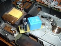
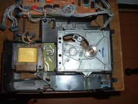
JeroenR said:I found some space for the clock powersupply. It should be not too high though as the drawermechanism also makes use of it. (see pics)
Did someone already install a clock? I have a Tent module (8MHz) and a 74HC74 to get to 4MHz. I know the 7000/7030 runs at this freq and I remember someone at this forum clocked the 7000/7030 with this. As I want to remove the 7030; what freq should I clock the DACS and how do I get two feeds from one XO module (if possible)? I have the manual but am not experienced enough to find the answer there.
Thanks,
Jeroen
Before doing anything I would suggest you get the datasheets for the SAA7000, SAA7030 and TDA1540.
I think you can use Kwak clock with original quartz oscillator and 74HCT74 for send clock to tda1540(if you don't use saa7030).
The output of Master clock to PIN8 of SAA7000 and PIN3 of 74HCT74
PIN12 of SAA7000 to PIN2 of 74HCT74
PIN5 of 74HCT74 to PIN2 of TDA1540
Bye
Andrea
The output of Master clock to PIN8 of SAA7000 and PIN3 of 74HCT74
PIN12 of SAA7000 to PIN2 of 74HCT74
PIN5 of 74HCT74 to PIN2 of TDA1540
Bye
Andrea
drews said:I think you can use Kwak clock with original quartz oscillator and 74HCT74 for send clock to tda1540(if you don't use saa7030).
The output of Master clock to PIN8 of SAA7000 and PIN3 of 74HCT74
PIN12 of SAA7000 to PIN2 of 74HCT74
PIN5 of 74HCT74 to PIN2 of TDA1540
Bye
Andrea

has anyone made any changes to the power supplies to the various chips. The SA70?0 all seem to use a 4.7uH inductor + 22uF cap. Could these be improved ?
Also the opamps have 47uF caps but these supplies also feed 11.2 & 2.5 digital supplies.
I notice two decoupling resistors on the decoder board near the opamps. These look promising BUT only service one channel (according to my reading of the schematic) underneath the other channels supplies are decoupled by 2 SMD's. I guess all 4 should be replaced with 1uH inductors ?
Andrea, I do not understand your schema. why is the 7000 connected to the 74HC74? Will this not introduce jitter? Is this reclocking a signal instead of the DAC itself?
I was more thinking of doing the direct 7000 to 1540 as described in the "remove saa7030" thread and connect the clock to the DAC (pin 28?)
rfbrw : Can you please send me the datasheet for the 7000, I would be very gratefull. And.... 3 "no-shaking" smilies suggest you know better. Why not include your solution in that post? (or the next") )
)
I was more thinking of doing the direct 7000 to 1540 as described in the "remove saa7030" thread and connect the clock to the DAC (pin 28?)
rfbrw : Can you please send me the datasheet for the 7000, I would be very gratefull. And.... 3 "no-shaking" smilies suggest you know better. Why not include your solution in that post? (or the next
)rfbrw said:
What?
I use this configuration, what does it means
:no :no :no ????
Bye
address?JeroenR said:rfbrw : Can you please send me the datasheet for the 7000, I would be very gratefull.
And.... 3 "no-shaking" smilies suggest you know better. Why not include your solution in that post? (or the next
drews said:
What?
I use this configuration, what does it means
:no :no :no ????
Bye
You cannot send MCLK directly to the TDA1540.If you are new to this the first might give the impression you could.
JeroenR said:Andrea, I do not understand your schema. why is the 7000 connected to the 74HC74? Will this not introduce jitter? Is this reclocking a signal instead of the DAC itself?
I was more thinking of doing the direct 7000 to 1540 as described in the "remove saa7030" thread and connect the clock to the DAC (pin 28?)
rfbrw : Can you please send me the datasheet for the 7000, I would be very gratefull. And.... 3 "no-shaking" smilies suggest you know better. Why not include your solution in that post? (or the next
Yes, you can connect saa7000 direct to tda1540 but the clock must be connect to pin 8 of saa7000 and the output (pin 14 of
saa7000) to pin 28 of tda1540.
rfbrw said:
address?
You cannot send MCLK directly to the TDA1540.If you are new to this the first might give the impression you could.
MCLK is master clock? If yes, I don't I write to connect MCLK directly to tda1540, I write that tha master clock must be connect to pin 8 of saa7000 and pin 3 of 74hct74.
The output of saa7000 (pin 14) connect to pin 28 of both dacs.
pin 12 of saa7000 to in 3 of 74hct74
Finally pin 5 of 75hct74 to pin 2 of tda1540.
If you don't use 74hct74 pin 12 of saa7000 connect directly to pin 2 of dacs
rfbrw: Can you please use the email link in my profile? It is active.
Any input on how to clock the 1540 directly? I remember also a comment from Guido Tent on this, he mentioned (I hope I remember correctly) that it was better to clock the 1540 then the 7000. I tried to find the post but could not find it in a reasonable time...
Next to waiting for other people's input I'll try to make a mockup of the schema this weekend. It will be put together from bits of this forum though.
Thanks,
Jeroen
drews [/i][B] Yes said:rfbrw: Can you please use the email link in my profile? It is active.
The forum email system does not allow attachments.
Any input on how to clock the 1540 directly? I remember also a comment from Guido Tent on this, he mentioned (I hope I remember correctly) that it was better to clock the 1540 then the 7000. I tried to find the post but could not find it in a reasonable time...
Next to waiting for other people's input I'll try to make a mockup of the schema this weekend. It will be put together from bits of this forum though.
Thanks,
Jeroen
The TDA1540P is a 14 bit chip. The SAA7000 is 14/16 bit chip. In normal use, connected to the SAA7030, it is in 16 bit mode. If you want to connect the SAA7000 to the TDA1540P, the SAA7000 has to be in 14bit mode or you lose the sign-bit and the MSB of the audio data.
The TDA1540P has no provision for MCLK so do not even think about clocking it directly from an oscillator.
SAA7000 Pin13 DLCF------>TDA1540P Lch Data Pin1
SAA7000 Pin15 DRCF------>TDA1540P Rch Data Pin1
SAA7000 Pin14 /CLCF----->TDA1540P L&R /CP Pin 28
SAA7000 Pin12 STR1------>TDA1540P L&R LE Pin2
SAA7000 14/*16 Pin16 connect to +5v via 1k resistor.
This statement makes as much sense as saying " Yes, you can change the spark plugs in the engine but the tyres must be round".
These are two separate issues. Pin14 is not 'the output' of anything. It a 14/16 bit burst clock for loading the input register of the following chip. Whether you have a new clock or retain the original clock is totally irrelevant to how the SAA7000 connects to the TDA1540P.
Yes I know that pin 14 is a 14/16 bit select.......
You don't understand what I have write, probabily because my english is not good.
I want say that is possible use a 74hct74 and for use it SAA7000 Pin12 STR1 must be connect to pin3 of 74hct74 and pin 5 of 75hct74 to pin 2 of tda1540. If you don't use 74hct74, the pin 12 of saa7000 must be connect directly to pin 2 of tda1540., is the same things that you have write............
The TDA1540P is a 14 bit chip. The SAA7000 is 14/16 bit chip. In normal use, connected to the SAA7030, it is in 16 bit mode. If you want to connect the SAA7000 to the TDA1540P, the SAA7000 has to be in 14bit mode or you lose the sign-bit and the MSB of the audio data.
The TDA1540P has no provision for MCLK so do not even think about clocking it directly from an oscillator.
SAA7000 Pin13 DLCF------>TDA1540P Lch Data Pin1
SAA7000 Pin15 DRCF------>TDA1540P Rch Data Pin1
SAA7000 Pin14 /CLCF----->TDA1540P L&R /CP Pin 28
SAA7000 Pin12 STR1------>TDA1540P L&R LE Pin2
SAA7000 14/*16 Pin16 connect to +5v via 1k resistor.
Nothing news, was posted some time ago by Pisky to post of "remove SAA7030".........
drews said:
Yes I know that pin 14 is a 14/16 bit select.......
Pin 16
Nothing news, was posted some time ago by Pisky to post of "remove SAA7030".........
I am aware of that thread.
- Home
- Source & Line
- Digital Source
- Philips CD104 tweaks