Re: Re: cd valve output stage
Hi.
Good price on the 6021's !
I have used these at B+ of 35v and they sound great ! [They do not need high B+]
Also on triodedick's site is a 'Transistor Eliminator' for cd output..
Andy
JeroenR said:
Thanks. That's the Thorsten stage mentioned earlier.
On www.triodedick.com I found an article on a mu-stage. This mu-stage would be an improvement over the above mentioned circuit. Interesting is that the second triode could be replaced by a MOSFET. Not sure about the size of these MOSFETs but this could mean a smaller (size/volume) circuit with just one twin-triode and two MOSFETs. From the transformer we could get 100V through voltage doubling of the 50V output, perhaps this would be enough. Started reading John F. Rider again as I could not even find the load in this mu-stage thing.......
Any clever ideas are welcome.....
I just bought five 6021's from Ebay.")
Hi.
Good price on the 6021's !
I have used these at B+ of 35v and they sound great ! [They do not need high B+]
Also on triodedick's site is a 'Transistor Eliminator' for cd output..
Andy
Re: Re: Re: cd valve output stage
A bit over three euro a piece was not that bad.
Had a look at the transistor eliminator. Thanks!! Now I have so many questions......
About the load for the DAC ... I tried to understand the 1540 datasheet but have some queries. The datasheet mentions a full scale current of min 3.8mA and max 4.2mA, for the voltage complience it is min -10mV and max 10mV. Does this now mean a swing from 0mA to 4mA or from 3.8mA to 4.2mA? And the 10mV complience.... Does this mean for a swing of 0.4mA that the load resistor needs to be R=10mV/0.4mA=25ohm? On TriodeDick's site it is mentioned that for (some) Philips DAC's a 22ohm is used (probably a bit under that 25 to stay within design limits regarding the voltage complience) so that would make sense. Or not?
And the filter.... The filter mentioned by Thorsten (simple R/C) is different from the one triodeDick (R/C/chokes..) uses. Which one would be the preferred one? Is there a good (hands on) book about this? I'm not afraid of i^2=-1.
I will first try Thorsten and next the mu-stage. After reading John F. Rider I can now sort of design a SE-stage, understand the Thorsten circuit but am in the dark about the mu-stage. Why is there a 1K resistor between plate V1 and grid V2 in the circuit on TriodeDick's site? Is that not the opposite of the function of a mu-stage as the signal on grid of V2 will be less with the 1K? Well... questions like that.
Thanks for any input!!!
poynton said:
Hi.
Good price on the 6021's !
I have used these at B+ of 35v and they sound great ! [They do not need high B+]
Also on triodedick's site is a 'Transistor Eliminator' for cd output..
Andy
A bit over three euro a piece was not that bad.
Had a look at the transistor eliminator. Thanks!! Now I have so many questions......
About the load for the DAC ... I tried to understand the 1540 datasheet but have some queries. The datasheet mentions a full scale current of min 3.8mA and max 4.2mA, for the voltage complience it is min -10mV and max 10mV. Does this now mean a swing from 0mA to 4mA or from 3.8mA to 4.2mA? And the 10mV complience.... Does this mean for a swing of 0.4mA that the load resistor needs to be R=10mV/0.4mA=25ohm? On TriodeDick's site it is mentioned that for (some) Philips DAC's a 22ohm is used (probably a bit under that 25 to stay within design limits regarding the voltage complience) so that would make sense. Or not?
And the filter.... The filter mentioned by Thorsten (simple R/C) is different from the one triodeDick (R/C/chokes..) uses. Which one would be the preferred one? Is there a good (hands on) book about this? I'm not afraid of i^2=-1.
I will first try Thorsten and next the mu-stage. After reading John F. Rider I can now sort of design a SE-stage, understand the Thorsten circuit but am in the dark about the mu-stage. Why is there a 1K resistor between plate V1 and grid V2 in the circuit on TriodeDick's site? Is that not the opposite of the function of a mu-stage as the signal on grid of V2 will be less with the 1K? Well... questions like that.
Thanks for any input!!!
Re: Re: Re: Re: cd valve output stage
Hi.
I'm not an expert on tubes and unfortunately I don't read Dutch !
However, as I understand the SRPP circuit, the top tube acts as anode load. It could also be replaced with a [5-10mA?] constany current source.
JeroenR said:
A bit over three euro a piece was not that bad.
Had a look at the transistor eliminator. Thanks!! Now I have so many questions......
About the load for the DAC ... I tried to understand the 1540 datasheet but have some queries. The datasheet mentions a full scale current of min 3.8mA and max 4.2mA, for the voltage complience it is min -10mV and max 10mV. Does this now mean a swing from 0mA to 4mA or from 3.8mA to 4.2mA? And the 10mV complience.... Does this mean for a swing of 0.4mA that the load resistor needs to be R=10mV/0.4mA=25ohm? On TriodeDick's site it is mentioned that for (some) Philips DAC's a 22ohm is used (probably a bit under that 25 to stay within design limits regarding the voltage complience) so that would make sense. Or not?
And the filter.... The filter mentioned by Thorsten (simple R/C) is different from the one triodeDick (R/C/chokes..) uses. Which one would be the preferred one? Is there a good (hands on) book about this? I'm not afraid of i^2=-1.
I will first try Thorsten and next the mu-stage. After reading John F. Rider I can now sort of design a SE-stage, understand the Thorsten circuit but am in the dark about the mu-stage. Why is there a 1K resistor between plate V1 and grid V2 in the circuit on TriodeDick's site? Is that not the opposite of the function of a mu-stage as the signal on grid of V2 will be less with the 1K? Well... questions like that.
Thanks for any input!!!
Hi.
I'm not an expert on tubes and unfortunately I don't read Dutch !
However, as I understand the SRPP circuit, the top tube acts as anode load. It could also be replaced with a [5-10mA?] constany current source.
Re: Re: Re: Re: cd valve output stage
I'm stuck.
Anybody???
JeroenR said:
A bit over three euro a piece was not that bad.
Had a look at the transistor eliminator. Thanks!! Now I have so many questions......
About the load for the DAC ... I tried to understand the 1540 datasheet but have some queries. The datasheet mentions a full scale current of min 3.8mA and max 4.2mA, for the voltage complience it is min -10mV and max 10mV. Does this now mean a swing from 0mA to 4mA or from 3.8mA to 4.2mA? And the 10mV complience.... Does this mean for a swing of 0.4mA that the load resistor needs to be R=10mV/0.4mA=25ohm? On TriodeDick's site it is mentioned that for (some) Philips DAC's a 22ohm is used (probably a bit under that 25 to stay within design limits regarding the voltage complience) so that would make sense. Or not?
And the filter.... The filter mentioned by Thorsten (simple R/C) is different from the one triodeDick (R/C/chokes..) uses. Which one would be the preferred one? Is there a good (hands on) book about this? I'm not afraid of i^2=-1.
I will first try Thorsten and next the mu-stage. After reading John F. Rider I can now sort of design a SE-stage, understand the Thorsten circuit but am in the dark about the mu-stage. Why is there a 1K resistor between plate V1 and grid V2 in the circuit on TriodeDick's site? Is that not the opposite of the function of a mu-stage as the signal on grid of V2 will be less with the 1K? Well... questions like that.
Thanks for any input!!!
I'm stuck.
Anybody???
Re: Re: Re: Re: Re: cd valve output stage
Hi.
Try these :-
http://img185.exs.cx/img185/2008/dacout6im.gif
http://members.chello.nl/~m.heijligers/DAChtml/Analogue/Final.html
Andy
JeroenR said:
I'm stuck.
Anybody???
Hi.
Try these :-
http://img185.exs.cx/img185/2008/dacout6im.gif
http://members.chello.nl/~m.heijligers/DAChtml/Analogue/Final.html
Andy
Re: Re: Re: Re: Re: Re: cd valve output stage
Hi Andy,
Thanks you very much for the help!! Projects from others always help and inspire. Funny to see that the highly regarded Heijligers/Tent DAC uses just a simple one-stage triode output and not some sophisticated circuit. Perhaps worth the try (even less components).
But... I need to know what filter I need between the 1540 DAC and I/V stage and how to calculate this. There is lots of info on the 1541/pcm63 etc but not for the (lesser regarded??) 1540. Some pointers and the title of a book/web-page would be great.
Thanks,
Jeroen
JeroenR said:
I'm stuck.
Anybody???
poynton said:
Hi Andy,
Thanks you very much for the help!! Projects from others always help and inspire. Funny to see that the highly regarded Heijligers/Tent DAC uses just a simple one-stage triode output and not some sophisticated circuit. Perhaps worth the try (even less components).
But... I need to know what filter I need between the 1540 DAC and I/V stage and how to calculate this. There is lots of info on the 1541/pcm63 etc but not for the (lesser regarded??) 1540. Some pointers and the title of a book/web-page would be great.
Thanks,
Jeroen
I'm trying to remove as much components as I can from the decoder board. The data from the laser seems to be split into two routes, one goes to the saa7010 through resistor 3515 and the other to a discrete circuit through cap 2516. Would anyone know what this discrete circuit is doing? Can I disable it?
I received the 6021 tubes that I bought from ebay, these tubes are cute. The seller had added a spare 6021 and a 6111 to play with.
Thanks,
Jeroen
I received the 6021 tubes that I bought from ebay, these tubes are cute. The seller had added a spare 6021 and a 6111 to play with.
Thanks,
Jeroen
Attachments
JeroenR said:............ Can I disable it?
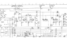
No.... if you have the manual, refer to page 6-1-a, the block diagram.
The extra bit of circuit is the drop out detector and provides signal to the motor stop control, track detector anddecoder amongst others.
Andy
poynton said:
No.... if you have the manual, refer to page 6-1-a, the block diagram.
The extra bit of circuit is the drop out detector and provides signal to the motor stop control, track detector anddecoder amongst others.
Andy
Hi Andy,
Thanks!!
I have the manual and indeed see the "drop-out hf level detector" block. Would you know what it does? What is a drop-out?
Jeroen
JeroenR said:
Hi Andy,
Thanks!!
I have the manual and indeed see the "drop-out hf level detector" block. Would you know what it does? What is a drop-out?
Jeroen
A drop out is an unreadable part on the cd.
The dropout detector sends signals to enable tracking to continue over the fault and also starts the interpolation etc. If the drop out is too long, it stops the motor.
It is connected to the error light [indirectly] a feature dropped on later cdps as it frightened customers !
poynton said:
A drop out is an unreadable part on the cd.
The dropout detector sends signals to enable tracking to continue over the fault and also starts the interpolation etc. If the drop out is too long, it stops the motor.
It is connected to the error light [indirectly] a feature dropped on later cdps as it frightened customers !
And again a bit wiser.
Thanks Andy.
Re: Re: Re: Re: cd valve output stage
No comments so far.
A shot at the filter : For the loadresistor for the DAC (TDA1540) I will use a 22ohm parallel with a 150nF C. This will give me the 10mV with a cutoff starting at 33kHz.
Does this make sense or am I completely wrong?
Thanks,
Jeroen
JeroenR said:
A bit over three euro a piece was not that bad.
Had a look at the transistor eliminator. Thanks!! Now I have so many questions......
About the load for the DAC ... I tried to understand the 1540 datasheet but have some queries. The datasheet mentions a full scale current of min 3.8mA and max 4.2mA, for the voltage complience it is min -10mV and max 10mV. Does this now mean a swing from 0mA to 4mA or from 3.8mA to 4.2mA? And the 10mV complience.... Does this mean for a swing of 0.4mA that the load resistor needs to be R=10mV/0.4mA=25ohm? On TriodeDick's site it is mentioned that for (some) Philips DAC's a 22ohm is used (probably a bit under that 25 to stay within design limits regarding the voltage complience) so that would make sense. Or not?
And the filter.... The filter mentioned by Thorsten (simple R/C) is different from the one triodeDick (R/C/chokes..) uses. Which one would be the preferred one? Is there a good (hands on) book about this? I'm not afraid of i^2=-1.
I will first try Thorsten and next the mu-stage. After reading John F. Rider I can now sort of design a SE-stage, understand the Thorsten circuit but am in the dark about the mu-stage. Why is there a 1K resistor between plate V1 and grid V2 in the circuit on TriodeDick's site? Is that not the opposite of the function of a mu-stage as the signal on grid of V2 will be less with the 1K? Well... questions like that.
Thanks for any input!!!
No comments so far.
A shot at the filter : For the loadresistor for the DAC (TDA1540) I will use a 22ohm parallel with a 150nF C. This will give me the 10mV with a cutoff starting at 33kHz.
Does this make sense or am I completely wrong?
Thanks,
Jeroen
you have mailFritz said:Jeroen,
Do you have the 104 schematics in a form that you could easily e-mail to me? I havent had luck eleswhere and could really use the information if your willing to send it.
Fritz
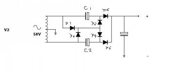
I created a powersupply for the tube I/V but have some trouble. The circuit is attached. The input is the 50V supply (55V measured unloaded) from the CD104 transformer. When the ground from the voltage doubler output is "hanging free" I measure 148V with no load so I guess the voltage doubler is working. But when I attach the groung/minus from the output of the voltage doubler to the ground/centertap from the 50V supply (which is used as groung in the player) then the transformer starts ..... well.... buzzing, snirping, an almost melting sound. Not good I think.
What am I doing wrong????
What am I doing wrong????
Attachments
JeroenR said:I created a powersupply for the tube I/V but have some trouble. The circuit is attached. The input is the 50V supply (55V measured unloaded) from the CD104 transformer. When the ground from the voltage doubler output is "hanging free" I measure 148V with no load so I guess the voltage doubler is working. But when I attach the groung/minus from the output of the voltage doubler to the ground/centertap from the 50V supply (which is used as groung in the player) then the transformer starts ..... well.... buzzing, snirping, an almost melting sound. Not good I think.
What am I doing wrong????
Ok, another try...
I attached another circuit (V2). Would that be better?
Thanks,
Jeroen
Attachments
JeroenR said:
Ok, another try...
I attached another circuit (V2). Would that be better?
Thanks,
Jeroen
Hi.
The problem is obvious.
The centre tap of the 50v AC windings [+-25v] is GROUND.
The output of the voltage doubler is floating around this point ie. +-74v wrt ground.
So, you CANNOT connect either side of the voltage doubler to GROUND as you are shorting out half your supply !!!! Hence the buzzing !

D1 and D2 short C1
D3 and D4 short C2
D2/D5 and D4/D6 are in parallel and act as a single diode
Andy
Attachments
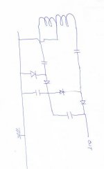
This may work ........
Hi.
This may work...
But I have not tested it....
I don't know what the ripple would be like.
It also requires another cap across the output ?
Both halves are working as full wave doublers.
The output of 1 is sat on the output of the other.
I dont think it will go BANG !
Andy
Hi.
This may work...
But I have not tested it....
I don't know what the ripple would be like.
It also requires another cap across the output ?
Both halves are working as full wave doublers.
The output of 1 is sat on the output of the other.
I dont think it will go BANG !
Andy
Attachments
- Home
- Source & Line
- Digital Source
- Philips CD104 tweaks