The image below is an excerpt from the schematic of a Philips/Magnavox CD-473 CD player (manuf. Aug. 1987). It uses the classic SAA7220/TDA1541 chipset.
This query is about the PSU and its + and - 15v supplies.
-15 volts is used by: TDA1541 (VDD2 rail); LM833 I/V and output stage opamp
+15 volts is used by: LM833 I/V and output stage opamp
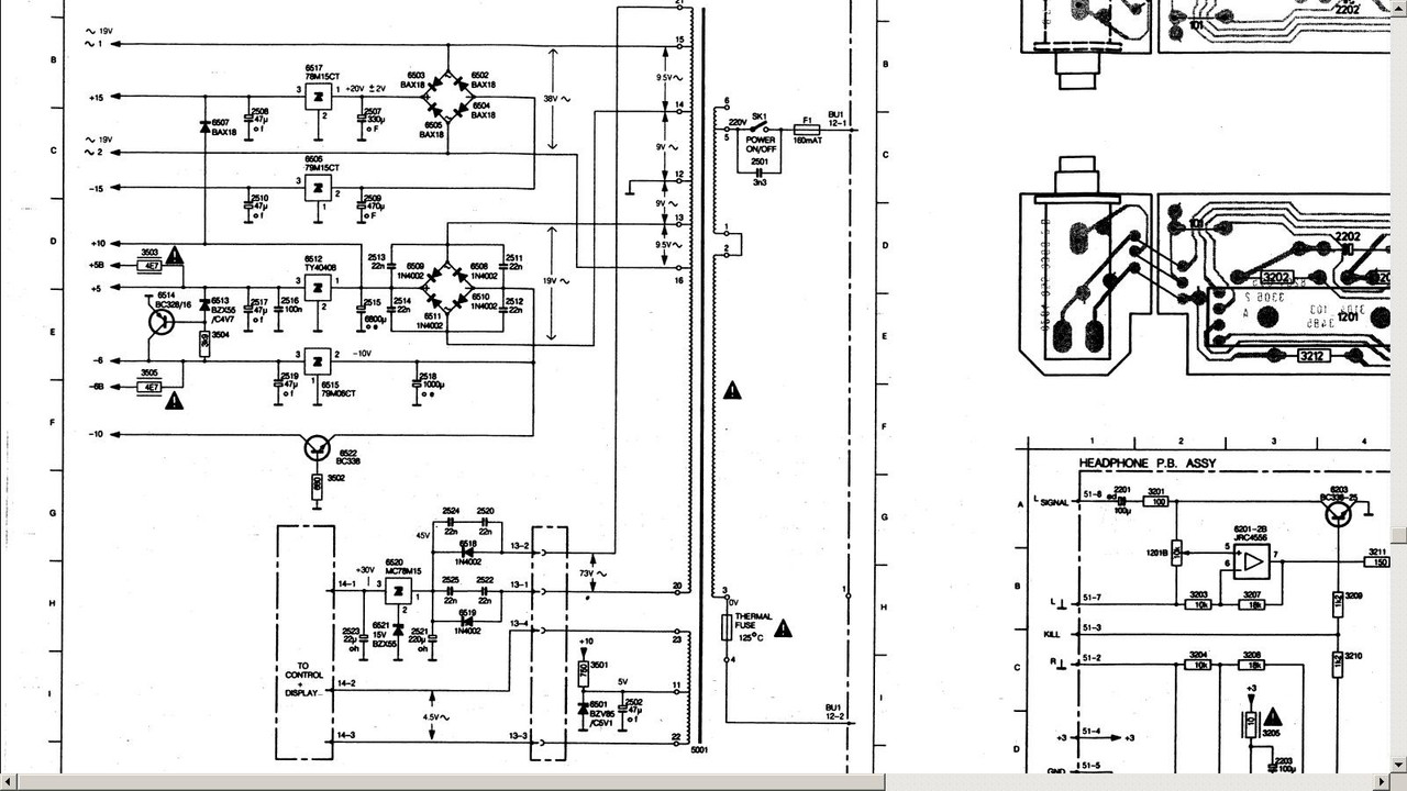
In the schematic, note the 78M15 and 79M15 regulators for +15 and -15 volts, respectively. Also note that main filter caps are: 78M15 (330uF) and 79M15 (470uF).
Questions:
(1) Why are the cap values different? E.g., Is it because the 79M15 has the greater current load, etc.?
(2) Why these capacitor values? Why not higher values -- such as 1000uF or higher? Is is because smaller-value caps cheaper; or is it because are 78xx or 79xx behave better with "smaller" filter caps?
Thanks!
This query is about the PSU and its + and - 15v supplies.
-15 volts is used by: TDA1541 (VDD2 rail); LM833 I/V and output stage opamp
+15 volts is used by: LM833 I/V and output stage opamp
In the schematic, note the 78M15 and 79M15 regulators for +15 and -15 volts, respectively. Also note that main filter caps are: 78M15 (330uF) and 79M15 (470uF).
Questions:
(1) Why are the cap values different? E.g., Is it because the 79M15 has the greater current load, etc.?
(2) Why these capacitor values? Why not higher values -- such as 1000uF or higher? Is is because smaller-value caps cheaper; or is it because are 78xx or 79xx behave better with "smaller" filter caps?
Thanks!
1. That is usually the reason more load so bigger cap.
2. Try the data sheets they show typical values and graphs showing performance.
Also try google I though I remembered a test that showed the results using different values but could not find it.
The ESR of the capacitor will be important.
What I normally do is replace same value with same value, just better quality capacitors.
Different Philips psu schemas -- of that period -- varied a bit depending on model. The CD-650, for example, uses 470uF for both 79M15 and 78M15.
Also, in some Philips models (or Philips-based models like Creek or Arcam), rectifier bridges for the +/- 15 supplies snub the bridge diodes with 22nF caps.
With the CD-473, only the rect. diodes for the +/- 5v supplies are snubbed with the 22nF caps. This indicates an economic decision.
Also, in some Philips models (or Philips-based models like Creek or Arcam), rectifier bridges for the +/- 15 supplies snub the bridge diodes with 22nF caps.
With the CD-473, only the rect. diodes for the +/- 5v supplies are snubbed with the 22nF caps. This indicates an economic decision.
In my early days, I experimented a lot with values.What I normally do is replace same value with same value, just better quality capacitors.
The reality, however, is that the OEM sunk all their development cost and skillset in that project. The component values and topology finally arrived at had the R&D budget of Philips, Sony, et. al.
Smaller cap values will tend to limit dissipation in the transformer. Big caps aren't always best as they draw far more current per charging cycle, but over less time. That can push a small transformer into saturation.
Also having different time constants (different cap sizes) between pos and neg rails may be a design feature to ensure the rails sequence better at start up thus minimising any latchup issue that may have come to light, or simply to minimise any switch on/off noise.
Also having different time constants (different cap sizes) between pos and neg rails may be a design feature to ensure the rails sequence better at start up thus minimising any latchup issue that may have come to light, or simply to minimise any switch on/off noise.
- Status
- This old topic is closed. If you want to reopen this topic, contact a moderator using the "Report Post" button.