I recently bought a NSM CD 3101 AC disc changer which cannot play CD-Rs, only the original pressed Audio CDs. I have a second unit of the same model and so far it could play any type of CD. So something must be wrong with my new CD changer.
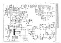
The CD changer has a Philips CDM4/53 transport and TDA8900, SAA7310 and SAA7321 ICs on the servo PCB. I found a service manual (incomplete) for the player and could upload the servo PCB schematic if needed.
What I did so far to solve the problem:
Those above mentioned steps were not successful. Somehow I think that the problem is related to the servo PCB but I really don't know what I should do next. Any help is highly appreciated.
The CD changer has a Philips CDM4/53 transport and TDA8900, SAA7310 and SAA7321 ICs on the servo PCB. I found a service manual (incomplete) for the player and could upload the servo PCB schematic if needed.
What I did so far to solve the problem:
- Cleaning the lens of CDM4 with IPA
- Replacing all the electrolytics on the servo PCB
- Checked the 3600 pF Polystyrene capacitor as suggested in another thread
- Checked the BC338 output transistor for the laser power supply
Those above mentioned steps were not successful. Somehow I think that the problem is related to the servo PCB but I really don't know what I should do next. Any help is highly appreciated.
Please find attached the schematic.
I forgot to mention that I checked the power supply as well. I could measure all expected voltage levels for the different supply rails.
I replaced all electrolytic caps with low ESR types of the same value except the bipolar 680 nF capacitor 2025 for the radial drive supply. I replaced that with a foil type capacitor. Do you think that the low ESR value of the replacement caps could cause a problem? I read in another thread that in some cases a higher ESR cap could be beneficial.
Attachments
Here's what I would do.
As you have another similar model I would begin by looking at the RF level on a scope and compare the good and bad unit. Do that on a normal disc.
Are they similar in amplitude and quality ?
Now put your CDR in the good player and see whether the amplitude and quality of signal is similar to the normal disc.
There are a lot of variables with CDR and some players cope better than others. So you need to do some initial measurements with a scope to see what is going on and whether the RF amplitudes are correct or marginal.
As the bad unit was already on my work bench, I started measuring the eye pattern from that with an original pressed CD:
It showed +2V DC offset and an amplitude of 0.75V. I think the amplitude is on the lower side for a CDM4. The signal looked clean.
I try to capture and upload an image later. I will test the good unit as well.
It showed +2V DC offset and an amplitude of 0.75V. I think the amplitude is on the lower side for a CDM4. The signal looked clean.
I try to capture and upload an image later. I will test the good unit as well.
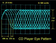
Like this. I would have thought around 1.2 volts from top to bottom for a Philips RAFOC. The signal will be sat on top of any DC voltage present but that is normal.
1.5 volts sounds a bit high but don't alter anything, just compare it with the good one using the same disc and measurement points. This picture shows 1 volt peak to peak.
1.5 volts sounds a bit high but don't alter anything, just compare it with the good one using the same disc and measurement points. This picture shows 1 volt peak to peak.
Attachments
I managed to capture the eye patterns:
- Good player - original CD - 1.3Vpp
- Good player - copied CD - 1.3Vpp
- Bad player - original CD - 1.3Vpp
Attachments
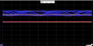
Well the amplitudes look OK and about what I would have expected. Thats good confirmation of that 
Can you make any determination of the 'quality' of the CDR signal ?
What we are looking for is jitter (is it steady) and the relative amplitudes off the T3 - T11 sinewaves that make the eye pattern up. All you can do is make an estimation of whether it looks OK on the CDR. Does the CDR waveform 'bounce'.
Its possible in the end that your problem is just down to tolerances, one player coping with it and the other does not. I suspect there will be no easy answer to this one
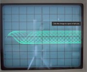
This is a real eye pattern I took a picture of (on an old Sony) and yours should look very similar. It should be rock steady. This was on a pressed commercial disc. Yours should be similar. The CDR will probably be less good.
Can you make any determination of the 'quality' of the CDR signal ?
What we are looking for is jitter (is it steady) and the relative amplitudes off the T3 - T11 sinewaves that make the eye pattern up. All you can do is make an estimation of whether it looks OK on the CDR. Does the CDR waveform 'bounce'.
Its possible in the end that your problem is just down to tolerances, one player coping with it and the other does not. I suspect there will be no easy answer to this one
This is a real eye pattern I took a picture of (on an old Sony) and yours should look very similar. It should be rock steady. This was on a pressed commercial disc. Yours should be similar. The CDR will probably be less good.
Attachments
Thanks for the explanation and the eye pattern example. It seems to be captured from an analog scope. I only have a simple USB-scope at home. I need to figure out the right scope settings first which I have to apply for the eye pattern measurement. I tried a mode called "digital persistance mode" which I never used before. Probably I could also borrow a better scope from work.
I already suspected that solving the CD-R issue won't be easy at all - but I don't give up so fast.
I will read about the eye pattern measurement now and provide new scope images soon.
I already suspected that solving the CD-R issue won't be easy at all - but I don't give up so fast.
I will read about the eye pattern measurement now and provide new scope images soon.
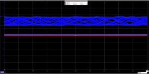
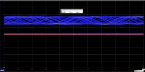
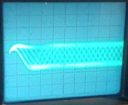
I found a cheap used analogue oscilloscope and captured the eye patterns again. I used 0.5 V/div and a timebase of 500ns. Sorry for the image quality. I hope you can get at least an idea of the signal quality.
The good player with original CD produces the best pattern - the pattern is stable and does not move at all. The eye pattern of the bad player oscillated quite a lot which results in a blurred photograph.
Probably it is worth mentioning that even the good player had some problems with the burned CD now. It was required to load it a second time, the first attempt gave rise to a "CD cannot be played"-error message.
To learn more about repairing CD players, I borrowed the book "Troubleshooting & Repairing Compact Disc Players" written by H. L. Davidson. I could not find time to read it yet, but the table of contents promises that it will be useful.
Attachments
They look reasonable enough. If you can see that the burned disc produces an unstable image then I think you have your problem, or at least part of it.
Some players just can not cope with the poorer signal a CDR/RW produces, however you can sometimes see a big difference in burning discs at different speeds. I found burning at faster speeds (which is against what you generally read) produced the best results on my burner.
As you have a scope that can accurately measure amplitude now, you could try increasing the laser power slightly by looking at the RF. Measure the amplitude accurately first on a known good Red Book disc (write the value down) and then increase the level a couple of hundred millivolts. Now see if the CDR plays or not.
Its really just for curiosity. If it doesn't help then reset the amplitude back to where it was on the same Red Book disc.
Thanks for your suggestion. Of course I am curious and want to see if changing the laser power could improve CD-R playing.
I just tried to find the pot for laser power adjustment on the servo PCB and in the schematic. Apparently, there is none
Is it possible that the laser power adjustment was done at factory by soldering a calibrated resistor? Could an IC on the servo PCB do the adjustment automatically?
While checking the PCB and schematic I saw that I forgot to replace a tantalum capacitor on a small attached ADOC PCB. It is for decoupling the +5V VDD for a PCF3523 IC. I read that it converts the I2C signal from SAA7310 to SPDIF. Do you think it is worth replacing the tantalum cap? Maybe it could affect the +5V rail somehow.
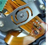
Ah, now I rember that I saw this preset when I once removed the CD drive. I did not dare to touch it because the whole drive/flexprint assembly looks really fragile.
There is no chance to reach the preset on the flexprint while the disc changer is assembled, it is necessary to remove the drive for the adjustment. To be honest, I don't want to risk damaging the laser with a trial and error approach.
Regarding the tantalum cap, I read about the HF rejection properties and I agree that I should not replace it with a different type of cap.
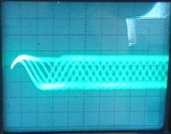
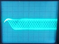
I checked my captured eye patterns again and realized, that they slightly differ from the textbook eye pattern that I saw:
After the first three strong peaks there is a small dip in the signal with lower amplitude compared to the average.
Anyway this effect is visible for all eye patterns that I recorded, even for the good player.
There is no chance to reach the preset on the flexprint while the disc changer is assembled, it is necessary to remove the drive for the adjustment. To be honest, I don't want to risk damaging the laser with a trial and error approach.
Regarding the tantalum cap, I read about the HF rejection properties and I agree that I should not replace it with a different type of cap.
I checked my captured eye patterns again and realized, that they slightly differ from the textbook eye pattern that I saw:
After the first three strong peaks there is a small dip in the signal with lower amplitude compared to the average.
Anyway this effect is visible for all eye patterns that I recorded, even for the good player.
TDA8900 voltages
Hello
I have issues with my CDM4I.
Please. Any of you are able to measure TDA8900 voltage between pins 28 and 29.
My reading is -3.74 volts; am not sure if it correct.
Seems it is bad.
Pin 2& is VSS and it is receiving voltage from -VM trough a 2k2 ohms resistor.
In the resistor -VM side is -9.7 volts and in VSS side is -3.74 volts.
Between pin 28 (VSS) and BGND is a capacitor, it is not in short circuit and also measuring pin 29 with pin 29 (BGND) it is having a high resistance.
Is really weird to have too much voltage dropping in that resistor.
Again, please help me with this issue.
Thanks
Claudio Bio
claudiobio2012@gmail.com
- Status
- This old topic is closed. If you want to reopen this topic, contact a moderator using the "Report Post" button.
- Home
- Source & Line
- Digital Source
- NSM CD 3101 AC (CDM4 transport) does not play CD-Rs