Hello
My Marantz cd5000 sounds great with the modifcations even with stock rca cable.
I noticed in the service manual 2505 and 2506 are capacitors , though both my Marantz and Philips have used resistors which i measured, and they are 2.27K ohms.
I have used CMF55 Dale and for the output resistors charcroft zfoil resistors. Decoupling capacitors are Mundorf Evo Oil.
Anyway back to 2505 and 2506, i have some RC55Y Welwyn resistors 15ppm. 0.1% tolerance at 2.26Kohm, not 2.27K? not sure what effect that would have, also voltage is 0.25w not sure of the watts of the original resistors, so i am tempted to try them but maybe is best to leave it , as is great already
My Marantz cd5000 sounds great with the modifcations even with stock rca cable.
I noticed in the service manual 2505 and 2506 are capacitors , though both my Marantz and Philips have used resistors which i measured, and they are 2.27K ohms.
I have used CMF55 Dale and for the output resistors charcroft zfoil resistors. Decoupling capacitors are Mundorf Evo Oil.
Anyway back to 2505 and 2506, i have some RC55Y Welwyn resistors 15ppm. 0.1% tolerance at 2.26Kohm, not 2.27K? not sure what effect that would have, also voltage is 0.25w not sure of the watts of the original resistors, so i am tempted to try them but maybe is best to leave it
, as is great alreadyAn externally hosted image should be here but it was not working when we last tested it.
An externally hosted image should be here but it was not working when we last tested it.
You should measure them one leg unsoldered.Thank you Percival, i measured it and got 2.27K ohm on ohm setting and thought it was a resistor in place of a capactior, a few capacitors that look like resistors on the board in the 2*** part numbers, maybe is best to leave or replace with wima of same value
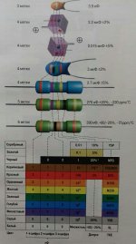
And the parts themselves say 470pF too, yellow, violet, brown, grey ,grey. That seems like outputsignal filtering with Y5R ceramic, looking at the resistors and electrolytics directly around these I guess you'll be replacing them with mica or cog or if you hate silver some metal film
See on page 4 of the data sheet and you know where the 2.27k Ohms are. It's Rconv 1 and Rconv2 .
http://www.lampizator.eu/lampizator/LINKS AND DOWNLOADS/DATAMINING/tda_1549.pdf
BR
Günni
http://www.lampizator.eu/lampizator/LINKS AND DOWNLOADS/DATAMINING/tda_1549.pdf
BR
Günni
What is the function of those capacitors in that circuit? In what way are the current components inadequate for this function?
Thanks for the reply DF96, at this stage i dont see why they are inadequate, but before i put it back together, i was curious if that was a point that could be upgraded as well
You should measure them one leg unsoldered.
Thanks for the reply lcsaszar, then i would realise it's a capacitor as i dont have capacitance on my multimeter
I think, he is measuring the internal resitnace between pin 5 and 4 also the same pin 6 and 7 of the DAC(filter outputs of the 1549). Acc. to service manual 2505 and 2506 are 470pF, the datasheet of the TDA1549 says 1nF.
Thanks for the reply Gunni, yes i was measuring only 2505/6 and they gave me 2.27k ohm on ohm settings, i dont have capacitance on my multimeter.
And the parts themselves say 470pF too, yellow, violet, brown, grey ,grey. That seems like outputsignal filtering with Y5R ceramic, looking at the resistors and electrolytics directly around these I guess you'll be replacing them with mica or cog or if you hate silver some metal film
Thanks for the reply Irribeo, The colours indicate its 470pf, the Y5R ceramic can also be axial? if they are ceramic them a film or mica would be good there.
See on page 4 of the data sheet and you know where the 2.27k Ohms are. It's Rconv 1 and Rconv2 .
http://www.lampizator.eu/lampizator/LINKS AND DOWNLOADS/DATAMINING/tda_1549.pdf
BR
Günni
Thank you Gunni, The 2.27K i get on 2505/6 is because they are in ciricuit? They are not 1Nf but 470pf, not sure why Marantz Philips did not use 1nF.

At first sight it seems that these caps should use linear dielectrics. However, given the low signal voltage (1.5V) and the highish corner frequency (150kHz?) it may be that Marantz felt they could get away with a bit of nonlinearity. I think I would want a linear dielectric, although I would not worry about brand.
Hi MccAU,
when you measure across 2505/2506 with a digtal multimeter, you will measure not the capacity of 2505, but you will measure the internal resistor in the feedback of the internal opamp of the TDA 1549 (see block diagram on page 4 pin7 and 4 of the TDA). the parts looking like resistors are axial capacitors (used quite seldom, better part are available, silver mica or COG type ceramics.
So there is no difference between schematics and equipped pcb. from my view there was no modifications done, and still not necessary.
Btw the CD5000 is a Philips cd753 in a different case. Same as the Marantz CD583 is a Philips CD584, only the case differs.
ok
Günni
At first sight it seems that these caps should use linear dielectrics. However, given the low signal voltage (1.5V) and the highish corner frequency (150kHz?) it may be that Marantz felt they could get away with a bit of nonlinearity. I think I would want a linear dielectric, although I would not worry about brand.
Thanks for the reply PF96
Hi MccAU,
when you measure across 2505/2506 with a digtal multimeter, you will measure not the capacity of 2505, but you will measure the internal resistor in the feedback of the internal opamp of the TDA 1549 (see block diagram on page 4 pin7 and 4 of the TDA). the parts looking like resistors are axial capacitors (used quite seldom, better part are available, silver mica or COG type ceramics.
So there is no difference between schematics and equipped pcb. from my view there was no modifications done, and still not necessary.
Btw the CD5000 is a Philips cd753 in a different case. Same as the Marantz CD583 is a Philips CD584, only the case differs.
ok
Günni
Hi Gunni
They look like resistors but are not, so a good 470pf Mica i will use as you suggested. The place i get stock only have Cornell Dublier Silver Mica capacitors. They would be better choice over like a Wima
I have both Marantz CD5000 and Philips CD753, same, except Marantz used 220uf and 330uf for one capacitor, but that is only difference.
http://au.element14.com/w/c/passive-components/capacitors/silver-mica-capacitors/prl/results?st=470pf
Thank you
Sam
- Status
- This old topic is closed. If you want to reopen this topic, contact a moderator using the "Report Post" button.
- Home
- Source & Line
- Digital Source
- Marantz CD5000 mods leave resistor or change