For all you who like the beautiful sound of TDA1540s but have trouble playing CD-R then this small mod might help playback.
This is specifically for the Marantz CD73 and Philips CD303 however experience shows that so many players from this era have the same decoder setup.
I've been playing around with these players now for some time, and can suggest many other changes to improve sound reproduction, and many things never to do even though they're on this site....
This focuses on the RF side on the top decoder board. People may suggest tampering with the mechanism however apart from a total re-cap I would highly advise against it.
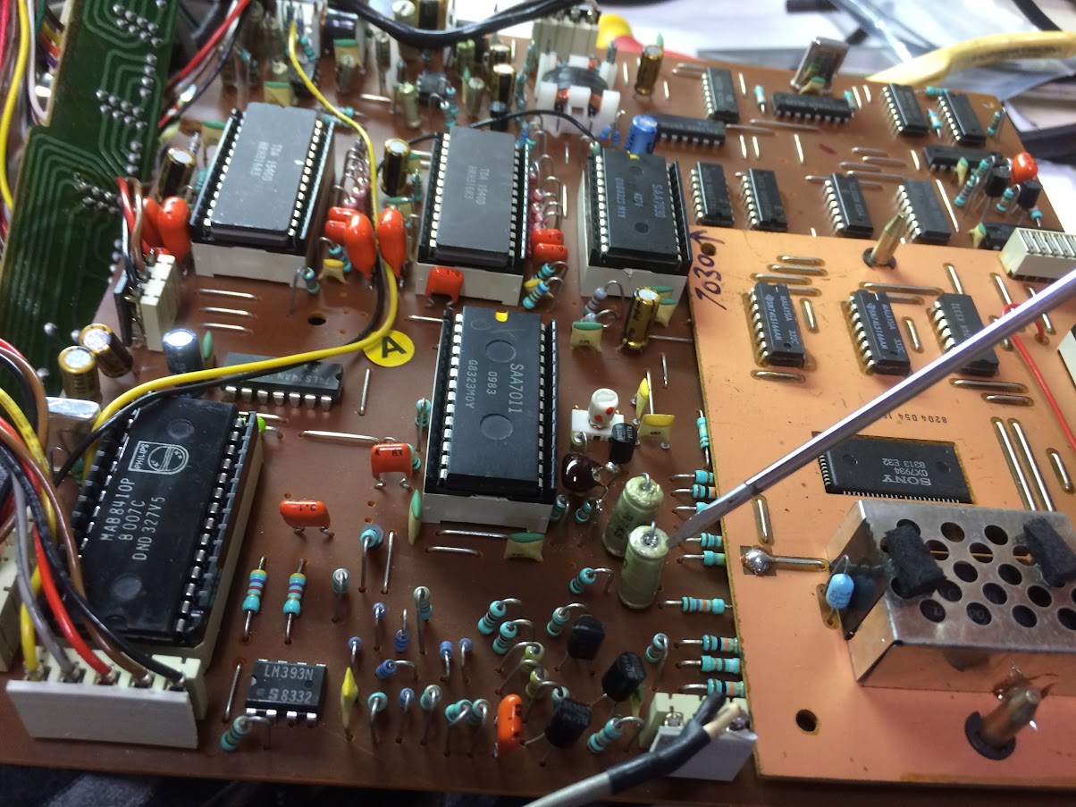
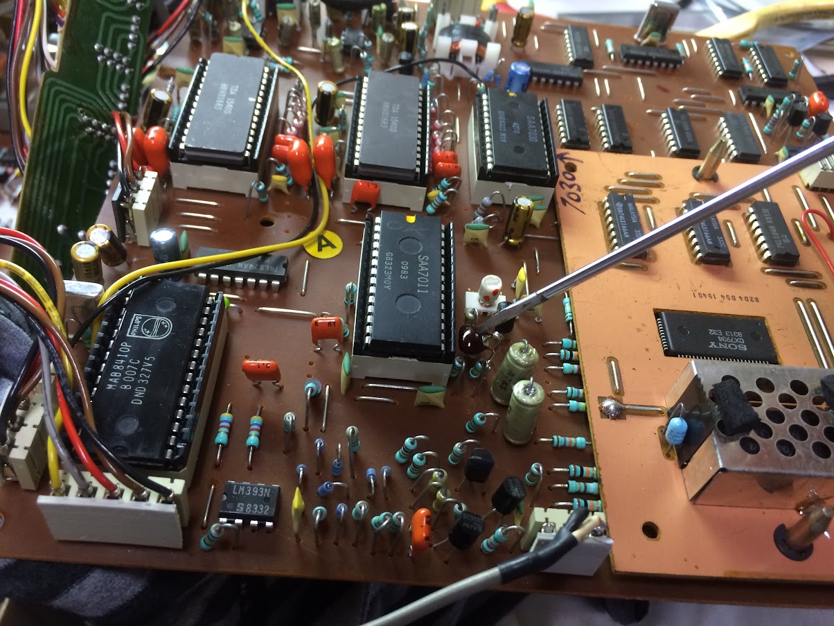
This is for the SONY decoder board, the Philips board is described below.
Capacitors 22nf near the SAA7011 are nice big RF foil antennas, degrading the RF. Pull these out and swap them around (reverse the polarity) putting the high impedance on the inside where it should be. This is easy 5 minutes work.
Solder a cap (I used a 8.2pf mylar) to the top of the resistor (part 3552) next to the de-modulator SAA7011 on one leg(this also goes to pin 13 of the SAA7011) and the other leg of the cap to the cap (part 2655) that goes to the SONY daughter board..
Almost there... you might have to decouple the clock a tiny bit, maybe one or two turns anti-clockwise. This is the white screw thing next to the SAA7011. Be careful the screw thread is weak. Some SONY boards use a mismatch of components. If this is the case the cap can be soldered on the track side of the board.
This is for the Philips board, 2 bottom pictures:
This mod would be interesting to many owners of these CD players, not just the Marantz CD73 but Philips CD300, Marantz CD44, 74 ect. Pretty much any identical chipset.
Again 22nf foil Capacitors near the SAA7011 need swapping around (reverse the polarity) as described above. Yellow arrow.
Inside this Philips CD303 there is a resistor with a ferrite bead next to the 7010 Decoder. You need a 220pF cap to go from this resistor (not the bead side) and to RF ground.
Have a look at mine, there was a nice place to put it that makes it look factory. Red arrow.
This is where you play a CD with the top open and IF NEEDED carefully decouple the clock one or two turns anti-clockwise (green arrow). My suggestion is find a CD-R that is scratched and had no chance of playing before and put it in, when playing decouple the clock to improve playback. When satisfactory stop playback then press play. If the CD wont track initially then you have decoupled too much. Screw it back half a turn at a time and press stop and play again. Once it plays satisfactory then test the player with proper store bought discs to ensure all is good.
The second last picture shows the block diagram of the decoder board and the red arrows show the location to connect the capacitor. This will mainly help those who want to adapt this to a player that is not a CD73 or CD303.
The Last picture is a close up view of the Philips decoder board for easier reference. The Blue arrow shows the electrical connection of the capacitor.
While you're there why not a recap? I prefer Nichikon fine gold series. Especially the two that pass the audio to the OPAMPS. I have also found decoupling the DACs with 100nf WIMA caps to be an improvement also....
Hope this helps others enjoy the glory of these 14bit(noise shaped) players! Feel free to comment on results. 🙂


This is specifically for the Marantz CD73 and Philips CD303 however experience shows that so many players from this era have the same decoder setup.
I've been playing around with these players now for some time, and can suggest many other changes to improve sound reproduction, and many things never to do even though they're on this site....
This focuses on the RF side on the top decoder board. People may suggest tampering with the mechanism however apart from a total re-cap I would highly advise against it.
This is for the SONY decoder board, the Philips board is described below.
Capacitors 22nf near the SAA7011 are nice big RF foil antennas, degrading the RF. Pull these out and swap them around (reverse the polarity) putting the high impedance on the inside where it should be. This is easy 5 minutes work.
Solder a cap (I used a 8.2pf mylar) to the top of the resistor (part 3552) next to the de-modulator SAA7011 on one leg(this also goes to pin 13 of the SAA7011) and the other leg of the cap to the cap (part 2655) that goes to the SONY daughter board..
Almost there... you might have to decouple the clock a tiny bit, maybe one or two turns anti-clockwise. This is the white screw thing next to the SAA7011. Be careful the screw thread is weak. Some SONY boards use a mismatch of components. If this is the case the cap can be soldered on the track side of the board.
This is for the Philips board, 2 bottom pictures:
This mod would be interesting to many owners of these CD players, not just the Marantz CD73 but Philips CD300, Marantz CD44, 74 ect. Pretty much any identical chipset.
Again 22nf foil Capacitors near the SAA7011 need swapping around (reverse the polarity) as described above. Yellow arrow.
Inside this Philips CD303 there is a resistor with a ferrite bead next to the 7010 Decoder. You need a 220pF cap to go from this resistor (not the bead side) and to RF ground.
Have a look at mine, there was a nice place to put it that makes it look factory. Red arrow.
This is where you play a CD with the top open and IF NEEDED carefully decouple the clock one or two turns anti-clockwise (green arrow). My suggestion is find a CD-R that is scratched and had no chance of playing before and put it in, when playing decouple the clock to improve playback. When satisfactory stop playback then press play. If the CD wont track initially then you have decoupled too much. Screw it back half a turn at a time and press stop and play again. Once it plays satisfactory then test the player with proper store bought discs to ensure all is good.
The second last picture shows the block diagram of the decoder board and the red arrows show the location to connect the capacitor. This will mainly help those who want to adapt this to a player that is not a CD73 or CD303.
The Last picture is a close up view of the Philips decoder board for easier reference. The Blue arrow shows the electrical connection of the capacitor.
While you're there why not a recap? I prefer Nichikon fine gold series. Especially the two that pass the audio to the OPAMPS. I have also found decoupling the DACs with 100nf WIMA caps to be an improvement also....
Hope this helps others enjoy the glory of these 14bit(noise shaped) players! Feel free to comment on results. 🙂
An externally hosted image should be here but it was not working when we last tested it.
An externally hosted image should be here but it was not working when we last tested it.
Last edited:
Hello TV7, could you explain what is the second mod doing? Also could you show it on the circuit digram? I might apply the mods on a CD74.
As far as I can tell the cap shunts some rf to a suitable sink, through experiment this appears as good a place as any to put it. I figure by reducing the rf a small amount allows the decoder to more easily interpret the signal. Cd-Rs being much more inclined to generate errors in transmission. But this is all in the rf domain and my old scope won't tell me much. Maybe someone can verify this later? I have also over clocked the MAB8410 which further improved error correction hence sound quality. Pretty sure meridian borrowed a clock and did something similar here. As for circuit diagram download the Philips service manual for the 303 and work it out. I listed the part numbers for easy reference.

No. I'm thinking that's the cd74 using the Philips chip set? That I found I had to do different. From trial and error there is a very specific size cap needed to make it work properly. But I would have to pull mine apart to remember how I did it. See if I get time later.
Hi TV7
Thanks for input. I have a a philips cd104. Plays ordinary cd's, but not cdr. Tried to reverse the 2 x 22nf - no improvement. By the way, there is no SAA7011.
I didnt do the small cap yet, because there is a 22 nf cap, not 100 nf like your diagram, next to the resistor. Should I use another size cap than the 220 pF ?
BR
Attachments

Hi TV7
Thanks for input. I have a a philips cd104. Plays ordinary cd's, but not cdr. Tried to reverse the 2 x 22nf - no improvement. By the way, there is no SAA7011.
I didnt do the small cap yet, because there is a 22 nf cap, not 100 nf like your diagram, next to the resistor. Should I use another size cap than the 220 pF ?
BR
I think in your case the problem lies elsewhere. The 104 like the Marantz cd44 had a much better shielded pcb and component layout. everyone I tried played cd-r with little trouble. Or though I could be mistaken. I would be looking at the laser making sure it's clean and replacing all electrolytics in the player first.
I think in your case the problem lies elsewhere. The 104 like the Marantz cd44 had a much better shielded pcb and component layout. everyone I tried played cd-r with little trouble. Or though I could be mistaken. I would be looking at the laser making sure it's clean and replacing all electrolytics in the player first.
Hi TV7
You´re probably right. I think, unfornutenately, its in the swing arm/laser adjustment.
I already did caps, nos-mod, griplets...a long time ago, and it actually played cdr´s with smalle errors + distortion. Then, in my eager to make it play vdrs flawlessly, I have been messing around incl. disambling the lower adjustment plate for the swing arm (and dont do this). I have put a lot of effort in readjusting - and im not there yet.
Saw your post and hoped....sorry, i didnt want to keep back information. I just keep trying to readjust the laser angle with the lower plate, it has to be possible.
From previous experience I feel your pain. I tried transplanting CDM1 and CDM0 parts and could never never! align the laser back to it's original setting. The same goes for 'tweaking' the trimmers on the CDM board. Once you do this be prepared for the hurt locker. Funny how the Marantz CD54 is essentially the same and the manual has good information on measuring voltages for laser height adjustment which the CD73 lacks. All the best of luck!Hi TV7
You´re probably right. I think, unfornutenately, its in the swing arm/laser adjustment.
I already did caps, nos-mod, griplets...a long time ago, and it actually played cdr´s with smalle errors + distortion. Then, in my eager to make it play vdrs flawlessly, I have been messing around incl. disambling the lower adjustment plate for the swing arm (and dont do this). I have put a lot of effort in readjusting - and im not there yet.
Saw your post and hoped....sorry, i didnt want to keep back information. I just keep trying to readjust the laser angle with the lower plate, it has to be possible.
Hi TV7,
Thank you so much for your info here about reading CDRs. I am going to try this on a CD-84 later and then my CD-54. My CD-104s, CDX and CD-73 with Philips board are all OK at reading Taiyo Yuden CDRs; but the Marantz players will play the first track but can't skip forwards or backards to orher tracks. They will not play anything but the intial track unless you fast forward through the CD until you get to the song you require - This is very annoying and you can hear the laser trying to get there but it never does.
One thing I don't understand is when you specify swapping the capacitors polarity - They have no polarity?
Regards,
Phil
When I say polarity I'm talking about reversing connections of the cap. These film caps don't have polarity but very old school shows an advantage to connect high impedance paths to the inside roll of the cap. This just helps the circuit to reject less undesirable inducted signals.
Good luck!
Good luck!
From previous experience I feel your pain. I tried transplanting CDM1 and CDM0 parts and could never never! align the laser back to it's original setting. The same goes for 'tweaking' the trimmers on the CDM board. Once you do this be prepared for the hurt locker. Funny how the Marantz CD54 is essentially the same and the manual has good information on measuring voltages for laser height adjustment which the CD73 lacks. All the best of luck!
Hi TV-7,
Unfortunatelly I realized the fact you mentioned above. I have a Marantz Cd-54 which started to misstrack during playback in some cd disks. Having already the issue of CDR's that Phildela describes below (...but the Marantz players will play the first track but can't skip forwards or backards to other tracks. ) so, I decided to replace the 5 caps 33uF on the CDM-1 board. I found in NOS the Philips brand 030 series caps, same value, that were identical to the original mounted , but before solder them I was shocked by measuring them between 16-22uF. Desoldering the old Philipsc caps I realized they were more or less the same capacitance (between 16-28uf). So I decided to replace by fresh 33uf Lelon brand (typical long life electrolytics). When I finishd I checked the player without connecting an audio output and everything seem to work flowesly. TOC in place, normal CD playback (flickering of leds) skip tracks by selecting buttons. CDR issue did not recover. TOC is found and can start the playback from 1st track only. Being very optimised for my project I dicided to replace a few decoupling caps on the servo board and also to adjust the turntable height and lazer output. Lazer was found at 640 mV at test point and adjusted to 500mV according to manual. Following the height adjustment instructions I set the point where the voltage accross the given resistor to be between +120mV to inner track and -135mV to outer track when player is in orizontal position. When in vertical all measuring are turned to more negative, funny isn't it I gave it a trial again , checked that everything was running "fine" as before and closed the case to run an audio test. Ohhh what a bad surprise. No audio out. Player starts normaly, indicating that normally plays the 1st truck, the led flicker but no output. By skipping forward to next tracks I found that only when arriving to last tracks it raises sound output for a few seconds, which then turn to distortion and sudently sound cut off. To make long story short, I tried many combinations between turntable height and laser output (returned to 600mV) and the best I managed it was to recover some seconds of music from the 2nd track and then, which again turns to distortion and output cut out (maybe throught it's tiny output relays). The same repeats by selecting track 3 and so on. Do you have any idea ? It seem like an offset disruption or maybe a circuit continuity problem. I hope I did not strech enough the flexi wire tapes when I droped out the CDM board to disolder caps. Another bad fear is that I misstuned the HF amp when changed the caps on CDM. I keep my hope alive as I still listen my beloved 54 for a few seconds under clean sound , by means probably can full recover again. One thing for sure, hopefully I did not touch other trimmers on the CDM board, like focus error and focus offfset. Anybody who has an idea will be highly wellcome.
Been a while sorry, been busy. How did you go? It really sounds like a focus issue. I suggest changing those coupling caps back to original for a start and check the polarity of the lytics you swapped out. After much stuffing around with these players as I said before the LAST thing you want to do is adjust the laser output and deck height. I found (after sacrificing many CDM0s and 1s) that the laser output sweet spot is such a fine, fine point on the trimmer as to be almost impossible to get back to factory set. Try adjusting the deck height back to a nice mid point and if youre lucky there will be some glue on the hex bolt that will give you an idea as to where you should be. From there try and get the laser trimmer adjusted a little at a time, bearing in mind at the factory they didn't go strict from the service manual and the actual value could be far removed from what it "should" be. At a certain power level the reflection will be a sweet spot and hopefully when you find this you can try and get the height better adjusted. Good Luck!Hi TV-7,
Unfortunatelly I realized the fact you mentioned above. I have a Marantz Cd-54 which started to misstrack during playback in some cd disks. Having already the issue of CDR's that Phildela describes below (...but the Marantz players will play the first track but can't skip forwards or backards to other tracks. ) so, I decided to replace the 5 caps 33uF on the CDM-1 board. I found in NOS the Philips brand 030 series caps, same value, that were identical to the original mounted , but before solder them I was shocked by measuring them between 16-22uF. Desoldering the old Philipsc caps I realized they were more or less the same capacitance (between 16-28uf). So I decided to replace by fresh 33uf Lelon brand (typical long life electrolytics). When I finishd I checked the player without connecting an audio output and everything seem to work flowesly. TOC in place, normal CD playback (flickering of leds) skip tracks by selecting buttons. CDR issue did not recover. TOC is found and can start the playback from 1st track only. Being very optimised for my project I dicided to replace a few decoupling caps on the servo board and also to adjust the turntable height and lazer output. Lazer was found at 640 mV at test point and adjusted to 500mV according to manual. Following the height adjustment instructions I set the point where the voltage accross the given resistor to be between +120mV to inner track and -135mV to outer track when player is in orizontal position. When in vertical all measuring are turned to more negative, funny isn't it I gave it a trial again , checked that everything was running "fine" as before and closed the case to run an audio test. Ohhh what a bad surprise. No audio out. Player starts normaly, indicating that normally plays the 1st truck, the led flicker but no output. By skipping forward to next tracks I found that only when arriving to last tracks it raises sound output for a few seconds, which then turn to distortion and sudently sound cut off. To make long story short, I tried many combinations between turntable height and laser output (returned to 600mV) and the best I managed it was to recover some seconds of music from the 2nd track and then, which again turns to distortion and output cut out (maybe throught it's tiny output relays). The same repeats by selecting track 3 and so on. Do you have any idea ? It seem like an offset disruption or maybe a circuit continuity problem. I hope I did not strech enough the flexi wire tapes when I droped out the CDM board to disolder caps. Another bad fear is that I misstuned the HF amp when changed the caps on CDM. I keep my hope alive as I still listen my beloved 54 for a few seconds under clean sound , by means probably can full recover again. One thing for sure, hopefully I did not touch other trimmers on the CDM board, like focus error and focus offfset. Anybody who has an idea will be highly wellcome.
Been a while sorry, been busy. How did you go? It really sounds like a focus issue. I suggest changing those coupling caps back to original for a start and check the polarity of the lytics you swapped out. After much stuffing around with these players as I said before the LAST thing you want to do is adjust the laser output and deck height. I found (after sacrificing many CDM0s and 1s) that the laser output sweet spot is such a fine, fine point on the trimmer as to be almost impossible to get back to factory set. Try adjusting the deck height back to a nice mid point and if youre lucky there will be some glue on the hex bolt that will give you an idea as to where you should be. From there try and get the laser trimmer adjusted a little at a time, bearing in mind at the factory they didn't go strict from the service manual and the actual value could be far removed from what it "should" be. At a certain power level the reflection will be a sweet spot and hopefully when you find this you can try and get the height better adjusted. Good Luck!
Thanks TV7, this is very encouraging!!
Why if I do it the experimental way, by means set the player the orizontal position, manage to get access for adjustments, connect the audio output and then very slowly search the laser sweet spot on the fly. Where the sound become continuous, there might be the point to lock. I'm wondering what should be the fisrt adjustment to start from. Turntable height of laser output. The laser at a confirmed working point (before modifications) was found at 640mV.
According to your advice the correct focus is more senitive to laser output, rather to height distance. Did I get it right? Thank you anyway for your kind support
Certainly if you know the 640mV original setting then adjust the laser to that as first starting point. Remember to check the caps! polarity on lytics and put the old film ones back. Some values of capacitance are very critical here, dont go changing to a higher value. Then adjust the turntable height to about mid way and slowly adjust the height, little up and try it, little down and try that, press stop then play again each time. Clean the lens with alcohol and a cotton bud well also. Hope you get it working!Thanks TV7, this is very encouraging!!
Why if I do it the experimental way, by means set the player the orizontal position, manage to get access for adjustments, connect the audio output and then very slowly search the laser sweet spot on the fly. Where the sound become continuous, there might be the point to lock. I'm wondering what should be the fisrt adjustment to start from. Turntable height of laser output. The laser at a confirmed working point (before modifications) was found at 640mV.
According to your advice the correct focus is more senitive to laser output, rather to height distance. Did I get it right? Thank you anyway for your kind support
Certainly if you know the 640mV original setting then adjust the laser to that as first starting point. Remember to check the caps! polarity on lytics and put the old film ones back. Some values of capacitance are very critical here, dont go changing to a higher value. Then adjust the turntable height to about mid way and slowly adjust the height, little up and try it, little down and try that, press stop then play again each time. Clean the lens with alcohol and a cotton bud well also. Hope you get it working!
No film caps have been replaced during modifications. All caps on CDM-1 board were Philips axial electrolytics at 33uF. They were 5 of them on. I replaced them with fresh radial elxtrolytics , the same capacitance. Their polarity was double checked when mounted ,so I feel there's no need to intervene there again. On the servo board I replaced 2 set of caps . First the 2 identical 330uf/16V electrolytics on the board DC supply inputs.They seem to be standard filter decoupling caps for possitive /negative supply lines. They replaced with equal value new ones. Another 2 decoupling 33 uf electrolytics next to chps supply rails, were replaced by new 33uF and 47 uF OSCON. I wiil check the polarity on all those 4. Last but not least before to start my experiment to adjust laser focus, I m going to replace the 1K laser pot with a good quality multiturn pot to accomodate the accuracy of adjustments. Do you think it's a good idea?
I wouldn't. You're introducing another unknown before you even get it working again.No film caps have been replaced during modifications. All caps on CDM-1 board were Philips axial electrolytics at 33uF. They were 5 of them on. I replaced them with fresh radial elxtrolytics , the same capacitance. Their polarity was double checked when mounted ,so I feel there's no need to intervene there again. On the servo board I replaced 2 set of caps . First the 2 identical 330uf/16V electrolytics on the board DC supply inputs.They seem to be standard filter decoupling caps for possitive /negative supply lines. They replaced with equal value new ones. Another 2 decoupling 33 uf electrolytics next to chps supply rails, were replaced by new 33uF and 47 uF OSCON. I wiil check the polarity on all those 4. Last but not least before to start my experiment to adjust laser focus, I m going to replace the 1K laser pot with a good quality multiturn pot to accomodate the accuracy of adjustments. Do you think it's a good idea?
I wouldn't. You're introducing another unknown before you even get it working again.
Noted !
Thanks
Certainly if you know the 640mV original setting then adjust the laser to that as first starting point. Remember to check the caps! polarity on lytics and put the old film ones back. Some values of capacitance are very critical here, dont go changing to a higher value. Then adjust the turntable height to about mid way and slowly adjust the height, little up and try it, little down and try that, press stop then play again each time. Clean the lens with alcohol and a cotton bud well also. Hope you get it working!
I spend some hours and I'm very optimistic that I will finally find again the sweet spot. I installed external lines to follow up the laser power voltage and also the height voltage.
I did my setting experιments on the fly with eys & ears alert. I realized as you mentioned that laser power is the key adjustment and that sweet spot is an absolutely fine point. I stepped up the laser supply voltage arround 240 mv and alter very slowly when sound came back at 248mv. Voltage slowly alters itself during normal disk palyback to next tracks. Sometimes the sound fails or breaks like bad connection. At that point I gave it some compensations with height adjustment. Height increase affects a bit inversely to laser voltage by decreasing 2-3 mv the laser out, while sound recovers until the next random brake to one of the next tracks. Finaly with many backs and forths, I managed to listen one complete cd and also verify that first track starts normaly when repeat. The funny thing is that laser voltage findings are different to other cd disks. Just to mention that by keeping the same settings other disks show the 1st track at 616mV while CDR's show 660mV. Some disks play sound from the 2nd track and others loose signal at the outer tracks. I'm in better condition than before, but I feel that need more accuracy to the laser pot adjustment (which the factory single turn pot does not provide) or I miss something else...What does the focus error and offset adjustment do?
- Home
- Source & Line
- Digital Source
- Marantz CD73 Philips CD303 improving CD-R playback