The last digits of the pickup serial number give the factory set current for the laser diode which should be easy to check by calculation after measuring the volt drop across a resistor in the laser drive circuit. 484 is it on yours ? That would be 48.4 milliamps if so.
Just performed this measurement on my "spare" KSS-151a laserunit in the Denon DCD-2560 EX which a bought as a donormachine with the help of the servicemanual on my new fine set of pins and grips for the MM.
I measured when running a disc 0.997 Volts voltagedrop.
According to the servicemanual I had to divide this value through 22 (as with the Wadia WT-2000 (Teac/Tascam P2S/CD-701) and the resulting value is 0.04531 A = 45.31 mA of iop.
Value on the KSS151a laser is 454, bingo only 1% lower than specified.
Seems a good buy this Denon DCD-2560 EX (What's EX by the way?)
You have to divide by the real value of the resistor which should be 20/22R, and after some warm-up. Only good DMMs can tell the story under very few ohms reading. BTW, with the "just slightly dirty" Wadia and the barely used Denon I call you a very very lucky guy! You should play lottery ASAP.
(EX for export and not JDM?)
(EX for export and not JDM?)
Last edited:
If the laser diode is worn out this value will be higher than the value on the sticker because of the optical power regulation. In case of a weak laser diode (lower emission) the optical regulation will increase the diode current to get the same optical intensity. BTW: That's why it's usually not a good idea to fiddle with the laser current/intensity.… bingo only 1% lower than specified.
It sounds a good result. The value of current is also affected by temperature, but what we were looking for was a noticeable increase (I think up to a 10% increase is quoted somewhere as a kind of limit) which would then point to a deteriorated diode and that obviously isn't the case here.
You have to divide by the real value of the resistor which should be 20/22R, and after some warm-up. Only good DMMs can tell the story under very few ohms reading. BTW, with the "just slightly dirty" Wadia and the barely used Denon I call you a very very lucky guy! You should play lottery ASAP.
(EX for export and not JDM?)
Forgot the warm-up period.After I let it play with the hood on for approx. 30 minutes the figure I got was: 1.020 Volts.
That translates to a iop 1.020/22 (that's the service manual indicating) = 46,45 mA. That's 1 mA higher then the spec (454) on the laserunit itself.
Still a good value of around 1% deviation.
The 'EX' is actually a golden badge on the front of the DCD-2560 reading "Reference EX - serie. probably a standard mod from Denon when the player was phased out of production. Didn't see anything reference like inside but hey I'm not a specialist in this area.
Player needs a new traybelt to function properly and that's something I alraedy did with a DCD-3560 which is a total different beast inside then this player. But the KSS151a seems alright.
How can I preserve the laserunit the best. Non playing at all. So now and then because of the rubbers inside the lens?
Just like Champagne turning the bottle for 180 degrees so now and then...Stock it upside-down half of the time =) Kidding... but that makes sens in fact! I can say intelligent stupid things, a new string on my bow (french direct translation...).
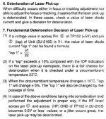
I also performed another measurement (4) (jitter related) that was in the servicemanual although the the indications what to do was not very clear see pictures from the servicemanual of the DCD-2560
http://www.diyaudio.com/forums/attachment.php?attachmentid=655511&stc=1&d=1515425851
http://www.diyaudio.com/forums/attachment.php?attachmentid=655512&stc=1&d=1515425851
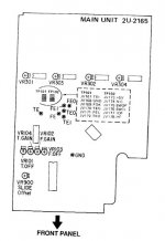
So at instruction 7 (4), pin 1 HF must be JVF178(HF) numbering starts from under to the top (Japanese) and GND?? just the ground pin or ground anywhere?
This sentence makes no sense:
".., if the HF level across pin (1) and across (HF) GND of TP102 in 2U-2165 becomes 0.6V or less..."
Maybe my English is not good enough but this instruction is pretty ambivalent to me.
I measured between pin (1) HF JVF178 and the ground pin (somewhat lower to the front of the player indicated with XGND 0.554V so that's not good and could indicate a deteriorated laser after all.
The laser is manufactured at 11 September 1992.
With the traybelt stretched which indicates a lot of use maybe it's not such a bargain after all...

Attachments
As far as I have seen, HF amplitude (on my scope so PP, don't know how a DMM see that with RMS values and if its bandwith allows HF) changes a lot with physical quality of CD itself.
I would keep the Iop value and nothing else, their HF stories are not clear enough. The brand new tray belt for my Tascam CD-401 lasted... 6 months?
Mooly, Anatech and other experts around?
I would keep the Iop value and nothing else, their HF stories are not clear enough. The brand new tray belt for my Tascam CD-401 lasted... 6 months?
Mooly, Anatech and other experts around?
As far as I have seen, HF amplitude (on my scope so PP, don't know how a DMM see that with RMS values and if its bandwith allows HF) changes a lot with physical quality of CD itself.
I would keep the Iop value and nothing else, their HF stories are not clear enough. The brand new tray belt for my Tascam CD-401 lasted... 6 months?
Mooly, Anatech and other experts around?
You use your CD-401 a lot
Thanks though.
I have a also a Fluke 27 without RMS reading is that better?
I wouldn't think usage would affect the life of a tray belt tbh. It runs for so little time that wear isn't really a factor, just aging and stretching.
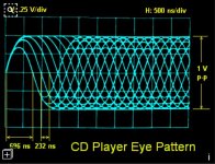
Without having a player in front of me to quickly check what is actually on those test points I would have said that HF = RF = Eye Pattern. Ask a technician 'have you checked the HF' and the assumption would always be that you meant the RF signal.
Checking the 'HF' would be done with an oscilloscope.
Your laser diode checks OK, but that is just the diode itself. You could prise the diode out of the pickup and the result would be the same, the current would be identical. That is because the optical laser power is measured by an internal photodiode embedded onto the same die as the laser diode.
If the HF is low and the laser power is good then that can mean a problem with the optics. A fogged lens will lower the 'HF' even though the actual laser diode is functioning correctly. Its like shining a torch with a dirty lens. The bulb is fine but the final light output might be low.
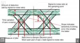
Jitter is something that an experienced tech can discern in the 'HF' when viewed on a scope. The signal should be clear and steady. If its noisy/jumpy and generally unsteady then we might say it had 'jitter'.
These images are from the web. The first is impeccably good, the second shows how jitter would look. Imagine all the 'diamond shapes' in the first image looking noisy like in the second.
I'm sure you have seen this thread of mine which gives real scope shots of RF. I would class this as 'good quality' RF
Sony CDP790 and KSS240 Restoration Project
Without having a player in front of me to quickly check what is actually on those test points I would have said that HF = RF = Eye Pattern. Ask a technician 'have you checked the HF' and the assumption would always be that you meant the RF signal.
Checking the 'HF' would be done with an oscilloscope.
Your laser diode checks OK, but that is just the diode itself. You could prise the diode out of the pickup and the result would be the same, the current would be identical. That is because the optical laser power is measured by an internal photodiode embedded onto the same die as the laser diode.
If the HF is low and the laser power is good then that can mean a problem with the optics. A fogged lens will lower the 'HF' even though the actual laser diode is functioning correctly. Its like shining a torch with a dirty lens. The bulb is fine but the final light output might be low.
Jitter is something that an experienced tech can discern in the 'HF' when viewed on a scope. The signal should be clear and steady. If its noisy/jumpy and generally unsteady then we might say it had 'jitter'.
These images are from the web. The first is impeccably good, the second shows how jitter would look. Imagine all the 'diamond shapes' in the first image looking noisy like in the second.
I'm sure you have seen this thread of mine which gives real scope shots of RF. I would class this as 'good quality' RF
Sony CDP790 and KSS240 Restoration Project
Attachments
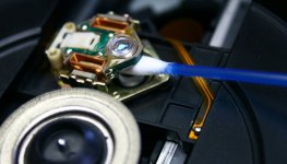
How about deepcleaning the lens like on the pages of the Lampizator:Nice link and work in the link. I'm always scared to clean the lens but there you've proven it's useful to do it. Ok where is my Tek and my Tascam...
http://www.diyaudio.com/forums/attachment.php?attachmentid=655584&stc=1&d=1515448551
Nice link and work in the link. I'm always scared to clean the lens but there you've proven it's useful to do it. Ok where is my Tek and my Tascam...
Thanks.
A good clean of the top surface of the lens can dramatically improve the level of the RF. That's something I've seen countless times when working on players.
Robert... your link doesn't work for me
Deep cleaning the KSS151a lens - Lampizator style
http://www.diyaudio.com/forums/attachment.php?attachmentid=655701&stc=1&d=1515500506
Better?
Credits: Lukasz Fikus, Lampizator archive website
http://www.diyaudio.com/forums/attachment.php?attachmentid=655701&stc=1&d=1515500506
Better?
Credits: Lukasz Fikus, Lampizator archive website
Attachments
Better
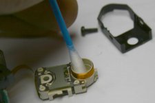
If you attempt anything like this then you need to be very careful. The picture shows the nylon suspension arms being lifted to what may be beyond their design limits. Also the cotton bud will not clean the underside of the lens, that needs to be removed to do that.
I have dismantled the Philips CDM12.4 in the past, but I did so by removing the lens suspension.
Stripdown/Clean of CDM12.4
I believe that's only possible with Philips LU's as the Lampizator website explains
Cleaning CDM1MkII, http://www.diyaudio.com/forums/attachment.php?attachmentid=655706&stc=1&d=1515502988CDM2, CDM4 from Philips
Credits Lukasz Fiskus
Cleaning CDM1MkII, http://www.diyaudio.com/forums/attachment.php?attachmentid=655706&stc=1&d=1515502988CDM2, CDM4 from Philips
Credits Lukasz Fiskus
Attachments
This is the complete link to his 'Laserology' webpage with IMO much relevant information about laserunits:
Laserology
Laserology
Can't help you out there I'm just a novice in this matter.Hmmm
This is the guy the made my aware that in my Wadia 6 or even 16 wasn't the same CD mechanism as in the Wadia 2000, 2000s or 7.
He has no it's own audio manufacturing business in Poland of mainly tube-amps an DAC's and combinations.
Of course the DIYaudio community is the biggest source of information and helpful and skilled people like yourself!
- Status
- This old topic is closed. If you want to reopen this topic, contact a moderator using the "Report Post" button.
- Home
- Source & Line
- Digital Source
- Wadia WT-2000 Transport