HI!
I have built the "Elektor DAC 2000" some time ago. Efter modding it with AD797 instead of OPA627 the sound has improved a great deal.
I would like to have switchable tube output though. Like the Shanling CD-players.
I need advice on:
1. What kind og tube design to add (SSRP, etc.
2. What kind of tubes. I have a few 12B4A, 6N1P, E80CC to try out.
3. Where and how to break in to mu exsisting circuit to add the new tube output.
Any ideas?
Best regards,
Peter Lund
Attachments
Audio note tube output stage
Ryssen,
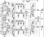
Take a look at this schematic: http://mparvi.republika.pl/DAC2sig_small.gif
It's a tube preamp output stage from an Audio note DAC with ECC88/6DJ8 in SRPP config and low voltage. Sound is said to be excellent.
What about adding it after the V-I stage?
- Peter
Ryssen,
Take a look at this schematic: http://mparvi.republika.pl/DAC2sig_small.gif
It's a tube preamp output stage from an Audio note DAC with ECC88/6DJ8 in SRPP config and low voltage. Sound is said to be excellent.
What about adding it after the V-I stage?
- Peter
The Ecc88 should work as well,I use 6SL7 because I like it better,
Here are some posts that I´ve done on the outputstage http://www.diyaudio.com/forums/showthread.php?s=&threadid=24297
I am going to use this stage with 6SL7.
http://www.diyaudio.com/forums/showthread.php?s=&threadid=6121&perpage=15&highlight=&pagenumber=1
I am going to try this I/V stage might work with the IC one on the board but you better ask sommeone who knows better than me,might be interesting for me to know to......
Konnichiwa,
You are aware that what Shanling does is to add a Cathode follower after the solid state audio circuitry? Is that what you want?
Whatever sounds good to you.
I personally use something rather different in a commercial mod set for Shanlings Tubed CD & SACD Player, but that circuit will not be available in the public domain. It provides great sound and excellent technical performance (Zout around 100Ohm, Frequency Response well into the MHz range, THD with WE396A is around 0.05 to 0.1% at digital full scale, less at lower levels), but the good old SRPP is not a bad choice, especially if the load is low.
Directly at the DAC output Pin.
ThanX for the Flowers....
Straight to pin14, all solid state parts disconnected.
Alternatively, if you wish to have both stages operational you could add a resistor (same value as intended I/V Resistor for Tube section) in series with inverting input of the I/V Op-Amp after the DAC.
However, this does not remove the Solid State circuitry from the signal path and hence the Valve Stage will retain a trace of "solid state" sound. I tried this forst for my Shanling Mod's as I intended to leave the solid state stage in place. I found it compromised the sound much more than I was happy to accept, so my mod's to the Shanlings dispose of the SOlid State section completely (the headphone Output is gone too).
Sayonara
jazzpeter65 said:I would like to have switchable tube output though. Like the Shanling CD-players.
You are aware that what Shanling does is to add a Cathode follower after the solid state audio circuitry? Is that what you want?
jazzpeter65 said:1. What kind og tube design to add (SSRP, etc.
2. What kind of tubes. I have a few 12B4A, 6N1P, E80CC to try out.
Whatever sounds good to you.
I personally use something rather different in a commercial mod set for Shanlings Tubed CD & SACD Player, but that circuit will not be available in the public domain. It provides great sound and excellent technical performance (Zout around 100Ohm, Frequency Response well into the MHz range, THD with WE396A is around 0.05 to 0.1% at digital full scale, less at lower levels), but the good old SRPP is not a bad choice, especially if the load is low.
jazzpeter65 said:3. Where and how to break in to mu exsisting circuit to add the new tube output.
Directly at the DAC output Pin.
jazzpeter65 said:The Thorsten Loesch tube dac project looks nice.
ThanX for the Flowers....
jazzpeter65 said:I just don't get if the V/I-stage is needed or if you can connect it straight to pin 14 of the PCM1704?
Straight to pin14, all solid state parts disconnected.
Alternatively, if you wish to have both stages operational you could add a resistor (same value as intended I/V Resistor for Tube section) in series with inverting input of the I/V Op-Amp after the DAC.
However, this does not remove the Solid State circuitry from the signal path and hence the Valve Stage will retain a trace of "solid state" sound. I tried this forst for my Shanling Mod's as I intended to leave the solid state stage in place. I found it compromised the sound much more than I was happy to accept, so my mod's to the Shanlings dispose of the SOlid State section completely (the headphone Output is gone too).
Sayonara
Hi,
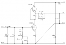
Those two alone aren't responsible for the de-emphasis IMO.
Where's the I/V done? Isn't that what's R1 for?
What's the B+ for the SRPP? Is it tightly regulated?
Cheers,")
It´s the one I´m talking about,but I am going to leave out the R1
Those two alone aren't responsible for the de-emphasis IMO.
Where's the I/V done? Isn't that what's R1 for?
What's the B+ for the SRPP? Is it tightly regulated?
Cheers,
Why leave out R1?
Ryssen,
Why do you want to use an active I/V converter circuit when the same function can be made by a simple resistor?
I think the whole idea of a simple analog output gets lost if you use an opamp for I/V. Most DACs exspect to send current into a virtual ground. In most cases in form of an opamp.
A load resistor is a more simple way to do this, but its not working with all DACs. Multibit DACs are not a problem, though. PCM1704 is multibit DAC. A load resistor will give less distortion than using an opamp. IMHO you should keep R1 since its a clever way of keeping the signalway short.
/ Peter
I agree that a resitor is simpler (shorter way) of doing I/V convert.
I got this advise "Try it, you won't be sorry" in this thread:http://www.diyaudio.com/forums/showthread.php?s=&threadid=6121&perpage=15&highlight=&pagenumber=9
Question number 2:I have read somewhere It sometimes sound
better with the right (Different value on the resistor)would it be possible to use variable resistor to find the right value?
http://www.diyaudio.com/forums/showthread.php?s=&threadid=31447
I got this advise "Try it, you won't be sorry" in this thread:http://www.diyaudio.com/forums/showthread.php?s=&threadid=6121&perpage=15&highlight=&pagenumber=9
Question number 2:I have read somewhere It sometimes sound
better with the right (Different value on the resistor)would it be possible to use variable resistor to find the right value?
I a´m thinking about it 2won`t solidstate regulators be better since they do not display any symtoms of noise?
http://www.diyaudio.com/forums/showthread.php?s=&threadid=31447
Konnichiwa,
May I suggest to all involved to re-read (or read) my short essay on Tubes and Digital from which these schematics are taken?
Thermionic Valve Analogue Stages for Digital Audio
I hope this will answer most questions sufficiently. You might also find some other essays and projects presented on my pages informative in the context, so please have a look:
the Thunderstone Audio Website!
Any remaining question, please ask in this thread.
Sayonara
Sayonara,
I have read your arcticles and so far, I get most of it. I have a few questions though, before I start building>
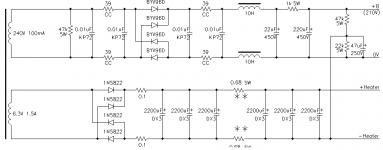
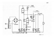
1. Would a regulated solid state PSU give a better signal-to-noise ratio? See attached circuit.
2. PSU: Can I substitute the special resistors for normal ones?
3. What do I have to change to use E80CC or 12Bb4H?
- Peter
I have read your arcticles and so far, I get most of it. I have a few questions though, before I start building>
1. Would a regulated solid state PSU give a better signal-to-noise ratio? See attached circuit.
2. PSU: Can I substitute the special resistors for normal ones?
3. What do I have to change to use E80CC or 12Bb4H?
- Peter
Attachments
- Status
- This old topic is closed. If you want to reopen this topic, contact a moderator using the "Report Post" button.
- Home
- Source & Line
- Digital Source
- DIY tube output in DAC - needs advice...