Hi,
Just fixed my naim cd3 with a donor 1541a dac as original was suffering bad distortion. Now there is no distortion but one channel has no bass whatsoever, the treble sounds nice and clear. Not sure where to look now. What could cause this?
Any suggestions greatly appreciated
Just fixed my naim cd3 with a donor 1541a dac as original was suffering bad distortion. Now there is no distortion but one channel has no bass whatsoever, the treble sounds nice and clear. Not sure where to look now. What could cause this?
Any suggestions greatly appreciated
Sounds an odd issue, particularly if replacing a part gives rise to another completely unrelated problem. I would concentrate on the area around where you worked.
Is it possible the original DAC was OK and the act of applying heat to remove it has altered what could be the same fault ?
Normally a lack of bass suggests an incorrect time constant in the analogue circuitry such as a cap that has significantly lost value. I'm not aware of any faults in the digital domain that would give rise to lack of bass.
As ever, the fault finding really requires a scope and for you to confirm (or otherwise) the problem at the earliest point in the analogue stages in order to say for sure whether the issue is analogue or digital in nature.
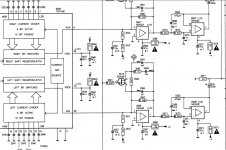
In the above diagram (and obviously refer to your actual player) you will see no measurable signal on pin 2 of the first opamp because it is configured as a virtual earth.
The output of the first opamp should be normal audio but with a little high frequency noise/hash superimposed on it.
The second opamp is actually drawn incorrectly. The - and + markings for the inputs are transposed. You should see clean audio on all three pins of this opamp.
In this diagram the 220uf cap would be the only component that would cause poor low frequency response. There may be further electrolytic coupling caps after this one and again they would be suspect. You should see the same audio signal on each side of the cap.
Also the DC voltages on all the opamps should be similar between channels. If the DC voltage is wrong on that first opamp then you are looking back toward the DAC.
You can as a test unsolder pin 2 of the first opamp (both channels) and cross link them to the DAC to see if the fault remains on the same channel or swaps over. If it stays the same its in the analogue section, if it swaps over then its in the DAC or earlier.
You can as a test unsolder pin 2 of the first opamp (both channels) and cross link them to the DAC to see if the fault remains on the same channel or swaps over. If it stays the same its in the analogue section, if it swaps over then its in the DAC or earlier.
An externally hosted image should be here but it was not working when we last tested it.
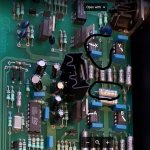
The signal input is only distorted at the opamp circled. I did find pio cap circled reads infinity on cap meter. Would this cause thid fault or something else? Can I replace this with a ceramic?
OK, so lets be clear on what you are seeing. Its never easy working from pictures like this.
The two points I marked as A and B which refer to pin 6 on the opamp... is the signal OK on those points and do both have the same DC voltage present ?
The points marked X and Y. I'm assuming the opamp is still an OPA604 (and not a 2604) and that the signal is incorrect on point Y (pin 6) and good on point X. Is that correct ?
I can't determine what the large circled cap does from the photo. It appears to be either a signal coupling cap or rail decoupling. Is the audio signal present on the cap ? If so then does it look the same at each end of the cap ?
Attachments
I really appreciate your help so far, I appreciate it's difficult without a schematic.
It now seems Ive lost the signal on the duff channel, I suspect it's on the cap circled, as the cap next to it has the signal on one end but the circled one doesn't. I suspect we have 2 faults here, I'll try and get it replaced to bring us back to where we where before. The voltages and signal are all fine until we get to opamp x, where there is zero output but I think thats because I now have lost signal. The voltages are wrong on pin 2 and 3 with 0v on pin 3 and 10.5 on pin 2.
I think I have an oc resistor somewhere, there is one with 3.3voltage drop across it just behind the regulator with the sink on.
The voltages on the opamp could be a clue because they are very wrong.
If you have zero volts on pin 2 and plus 10.5 on pin 3 then you should be seeing negative 10 or more on the output pin 6.
It would be interesting to confirm that.
There doesn't look to be much circuitry around that final opamp and it could be configured as a buffer with pin 2 and pin 6 linked. Its important to check this because that would directly contradict the readings you seem to get... so we need to check.
With the power OFF you need to see if there is direct continuity between pins 2 and 6 on the good and bad channel. If by chance there is then at least one problem is directly related to the opamp, either the device itself or something physical such as cracked print or a solder blob somewhere shorting something.
only just spotted this thread, so - following Mooly's last post -
Be aware the two opamps in series are each arranged as a 3-pole Sallen-Key low-pass filter, so two in series - the Naim output stage is a 7-pole Bessel alignment with the first pole at the I/V stage (a third opamp not in pic above)
It could indeed be that something has gone wrong with the large polystyrene cap; not seen this myself, but easy to do if you've ever waved a soldering iron near one! (PS melts at 80degC...)
HTH.
Last edited:
Ive replaced the ps cap, it looks like I may have killed it. So we are back to the start. So to clarify, I have 10v on input and output of the final opamp whereas all the other opamps in the good channel show 3.3v. With the input being 10v would it be safe to say the problem lies around this area?
Im lost now, every opamp on the board matches its counterpart in the good Channel except this one. I don't understand where the 10v is coming from. The only thing I can see is wrong is that there are some ps caps next to this opamp with 10v on one side and 3.3 on another but I suspect this is just on the same trace as the input. I can't find anything else with 10v on it.
Thanks again for your guidance, I will fix this!
Thanks again for your guidance, I will fix this!
Just to clarify the measurements, pin 2 and 6 are connected on the board and measure 10.5v, Pin 3 has 3.4 on which matches all the other opamps measurements. Is there a way I can tell the opamp is a duffer quickly without having to switch them over?
This is why I wanted to be 100% on this.
Pin 2 connected to pin 6 configures the opamp as a 'buffer'. This configuration means that the DC voltage on pin 3 (the non inverting input) should be exactly mirrored on the output pin 6.
So if you have 3.4 volts on the input pin 3 then that same voltage should appear on pin 6.
There are only three possible options (ha
") famous last words).
famous last words).1/ The opamp is duff.
2/ One of the supplies to pin 4 or 7 is missing.
3/ There is a 'short' from another part of the circuit to pin 6. If this were the case then opamp would be noticeably hotter than the other.
- Status
- This old topic is closed. If you want to reopen this topic, contact a moderator using the "Report Post" button.
- Home
- Source & Line
- Digital Source
- Naim cd3 no bass on one channel