Hy,
i will check out it next week. I will beginn with the two caps at pin 7 and 1 of op amp an listen without the muting transistors. I don't want it inside the signalpath, and i haven't any problems without mutingstage up to now.
@ dragonmaster : Do you allow to publish your scematic on my HP for information ? If not, do you have a HP with this drawing so i can put a Link ?
I will report the results next week.
Thanks at all
i will check out it next week. I will beginn with the two caps at pin 7 and 1 of op amp
I don't think it will work. I think jives11 tried something similar and the opamp killed the sound just because it's input and output were connected together.
Do you allow to publish your scematic on my HP for information ? If not, do you have a HP with this drawing so i can put a Link ?
If you want, but it's not a final version.
I do have a website but the playstation modifications are still not there. I will finish everything before starting it.
I'll try to explain how i do it 5 minutes ago ;-))
I soldered out c428 and C427 (this are the caps at pin 1 and 7 of op ) I soldered out C429 and 430 (this are the caps at pin 16 and 15 of AVM before 18K).I soldered a wire to the neg. piont of C429 and one at the neg. point of C430. I connected this wires with new caps . From the second contact of the new caps i soldered a wire to a foreign RCA +(not the RCA of the PS ). Than i soldered a wire from RCA - to a grd point near the AVM. Than i soldered a 1M resistor parallel to the RCA jacks. It works !!
I don't know how it sounds because i checked it with my second PS. Next week i will modify my other and connect it with my system
@dragonmaster : Thanks, you're right, sometimes it's better to wait until all is finished
well I followed dragonmaster instructions and removed all 6 caps.
I them shorted the input of the first cap pad (+ve) to the output of the last cap pad (also +ve ? which I still don't understand)
anyway I followed the pdf that Dragonmaster did.
I decided not to remove all DC blockers as I might use with a different amp in the future (T-amp) so didn't want to leave a surprise for myself
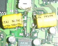
So I used a pair of Nitai 100uF/16v bipolars to join the pads
As Dragonmaster described I desoldered one pad and bent the old caps back. Most actually came away at this point. I then melted each pad to give a nice solder dome for each one. it was then easy to solder the caps on their side (not much height clearence ). An axial would be easier here.
Sound is better for sure. More bass, and none of the slight grittiness I perceived before. I could use a bit more bass, but maybe that needs more PSU work.
I them shorted the input of the first cap pad (+ve) to the output of the last cap pad (also +ve ? which I still don't understand)
anyway I followed the pdf that Dragonmaster did.
I decided not to remove all DC blockers as I might use with a different amp in the future (T-amp) so didn't want to leave a surprise for myself
So I used a pair of Nitai 100uF/16v bipolars to join the pads
As Dragonmaster described I desoldered one pad and bent the old caps back. Most actually came away at this point. I then melted each pad to give a nice solder dome for each one. it was then easy to solder the caps on their side (not much height clearence ). An axial would be easier here.
Sound is better for sure. More bass, and none of the slight grittiness I perceived before. I could use a bit more bass, but maybe that needs more PSU work.
Jives, why do you use such a terribly high capacity? Its just a DC blocker, so something in the 1 to 10 uF range should be sufficient. I was thinking about 4.7 uF as these are available as small polyester type (e.g. Wima), which should sound inherently better than any electrolytic.
Mick
Mick
Mick_F said:Jives, why do you use such a terribly high capacity? Its just a DC blocker, so something in the 1 to 10 uF range should be sufficient. I was thinking about 4.7 uF as these are available as small polyester type (e.g. Wima), which should sound inherently better than any electrolytic.
Mick
good question. I recall that most of the old Marantz CD players used around 100uF DC blocker . I recall that lower than this there was some bass rolloff ? maybe I'm wrong.
What is the diameter of 10uF polyester ? You may find there is not enough height due to the metal "roof" that has the CD trasport on top.
DragonMaster said:Well, what you've done seems right.
Now, I plan building a new PSU like back.
back, what regulators did you use finally, and can you provide a scheme? Last question, are the regulators heating a lot?
good evening everybody.
now that i heard a few cd`s i will tell one thing.
WOW!!
the psu makes a lot of a difference.
at last i used a 13.8v 7 amp psu with 10.000uf at the exit and after that i used i used two lm317k driving two 2n3055.
the regulators are cool but the transistors get vey hot.
especially the one with the 3.6volt becomes very hot.
here is the schematic:
http://ourworld.compuserve.com/homepages/Bill_Bowden/page12.htm#317pass.gif
i made the 3rd one "high current regulated supply" but with only one 2n3055 for every voltage and i added a 1000uf cap at the output of each transistor.
if you do this use separate windings or separate transformers for each voltage (3.6v and 7.6v) because the motor spinning (7.6)causes riple to the other voltage (3.6).
Dommi said:Hy,
i have a question : What is the PSU ?
Jives, Dragonmaster, what du you meen with "pad" ?
Pa
d is the solder point on the boa
rd. when i removed the caps it exposes two 'pad's where the cap was soldered. I reheated these to give a nice little 'dome' before i soldered my new dc blocker.
er diodes and caps...
I guess I had LED on the mind...therefore diode stuck in my head..
Any comments on the preferred method for the additional addition of light noise? white or blue, with the sled, or stationary?
As far as power supplies, do you think it is a linear power supply or the higher current that is responsible for the effects reported ?
The use of a higher current capable power supplies is a well known"tweak" for many devices including DACs and amplifiers of most types within limits.
The present state of my PS is out of the box, safety disabled, jumpers between cap pads as per dragonmaster.
jives11 said:
good question. I recall that most of the old Marantz CD players used around 100uF DC blocker . I recall that lower than this there was some bass rolloff ? maybe I'm wrong.
What is the diameter of 10uF polyester ? You may find there is not enough height due to the metal "roof" that has the CD trasport on top.
It depends on the resistor you are using in combination with the cap. The formula for the -3dB point is 1/(2*Pi*R*C). If the resistor is very small you should use a large capacity.
I think there are no 100 uF polyester caps. The highest value I know of this type is 4.7uF. The size is about 6 by 6 mm and about 10 mm height. If you combine it with a 22k ground resistor you have a cutoff frequency of 1.5 Hz.
Mick
Mick_F said:
It depends on the resistor you are using in combination with the cap. The formula for the -3dB point is 1/(2*Pi*R*C). If the resistor is very small you should use a large capacity.
I think there are no 100 uF polyester caps. The highest value I know of this type is 4.7uF. The size is about 6 by 6 mm and about 10 mm height. If you combine it with a 22k ground resistor you have a cutoff frequency of 1.5 Hz.
Mick
Thanks Mick
So what would the resistance to ground be in the case where we just removed the 6 caps ?
With these caps a) I had these caps in my parts bin and b) the signal goes through 4 of them up stream in the preamp anyway.
below is a picture showing that a) my photography is getting slightly better but b) my soldering shakes have taken there toll on the poor old saftey switch at the top
 still works though !
Attachments
SM PSU mods ?
Backs PSU mods are very interesting BUT , I'd like to keep the form factor of the unit "as is" with 250v AC directly to the unit. Which means sticking with the internal Switch mode.
Has anyone tried modding it ? I wondered if better caps (OSCONS) might lower the noise level while retaining the high current.
I also wondered if there is a way to increase the attenuation on the interconnect cable between the two boards. Mine has 2 ferrite cores, but is there a way if placing ferrite beads around each wire ? hard to disassemble the interconnect, can you get split beads which glue together around a cable which is already terminated for example ?
Hy Jives,
why you don't connect the caps direkt to the RCA ? The muting stage semms to be a bottleneck.
I don't know if i understood you right, but i modified the original PSU. I soldered out all caps and renewed them by Mundorf caps. Than i renewed the Diodes by faster ones.
BR Dommi
why you don't connect the caps direkt to the RCA ? The muting stage semms to be a bottleneck.
I don't know if i understood you right, but i modified the original PSU. I soldered out all caps and renewed them by Mundorf caps. Than i renewed the Diodes by faster ones.
BR Dommi
Hy @ all,
you know about my fake with the caps C424 and C423.
Now my question. Is it possible that whan i remove the caps C423 and C424 the load for the AVM is an other and therefore it sounds different ?
I ask because im not the only one who heard a difference between the old an new caps
And some of them argued (?? ) with the total load change of the AVM.
I hope you can follow my english
regards Dommi
Re: SM PSU mods ?
hi the LM338 is the way to go.
i couldn`t find that`s why i did all that but 5A is enough.
the one i made delivers 7A.
use a transformer 2 X 12 volt and use one winding for each voltage.
jives 11 i don`t understand who is stoping you from putting the new psu in the same box with the PS1 and run only one cable to the wall.
one new heavy box is needed anyway.
DragonMaster said:Hi back,
your link seems interesting but I don't know if I'll just go with LM338s in my case. It seems a bit complicated to work with it, especially the multiple transformers.
hi the LM338 is the way to go.
i couldn`t find that`s why i did all that but 5A is enough.
the one i made delivers 7A.
use a transformer 2 X 12 volt and use one winding for each voltage.
jives11 said:Backs PSU mods are very interesting BUT , I'd like to keep the form factor of the unit "as is" with 250v AC directly to the unit. Which means sticking with the internal Switch mode.
Has anyone tried modding it ? I wondered if better caps (OSCONS) might lower the noise level while retaining the high current.
I also wondered if there is a way to increase the attenuation on the interconnect cable between the two boards. Mine has 2 ferrite cores, but is there a way if placing ferrite beads around each wire ? hard to disassemble the interconnect, can you get split beads which glue together around a cable which is already terminated for example ?
jives 11 i don`t understand who is stoping you from putting the new psu in the same box with the PS1 and run only one cable to the wall.
one new heavy box is needed anyway.
Re: Re: SM PSU mods ?
Thanks back. I assumed that a linear PSU capable of supplying the current equal to the Switched Mode would be physically too big to fit in the PSone case, in the cavity left by the old PSU (transformer size etc)
I don't want to use an external DC supply (brick/wallwart style) as I don't really have the space.
back said:
jives 11 i don`t understand who is stoping you from putting the new psu in the same box with the PS1 and run only one cable to the wall.
one new heavy box is needed anyway.
Thanks back. I assumed that a linear PSU capable of supplying the current equal to the Switched Mode would be physically too big to fit in the PSone case, in the cavity left by the old PSU (transformer size etc)
I don't want to use an external DC supply (brick/wallwart style) as I don't really have the space.
- Home
- Source & Line
- Digital Source
- Playstation as CD-player