I look at your pics and the 4 pins on the right of the chip are unused.
Since AVM is compatible with B, it would mean that pins 1-10 are the good ones on the datasheet and that 11-20 are 15-24.
They also state that the pin 4 has a function with the AVM but not the B.
So here should be the pinout if I'm right:
1. TST1
2. DVDD
3. DVSS
4. /PB
5. /RST
6. MCLK
7. CKS
8. BICK
9. SDATA
10. LRCK
11. NC
12. NC
13. NC
14. NC
15. AOUTR
16. AOUTL
17. VCOM
18. AVDD
19. AVSS
20. NC
21. NC
22. VREFH
23. VREFL
24. DZF
Wow

WOW Mick. So apart from Photography, you build nanobots by hand as well ? As my dad used to say " it takes a steady hand to split the atom".
So .... is it worth it? Was there much improvement ? My experience with an old CD104 philips player was that these caps did make a big difference to the sound.
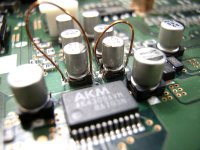
Mick_F said:Difficult, yes. But not impossible.
Just to give you a scale: The diameter of the wire is 0.3mm, the diameter of the caps is 3mm.
")
WOW Mick. So apart from Photography, you build nanobots by hand as well ? As my dad used to say " it takes a steady hand to split the atom".
So .... is it worth it? Was there much improvement ? My experience with an old CD104 philips player was that these caps did make a big difference to the sound.
But now that I look at it, there are connections to pins 11-14...
I also found a soldering joint between pins 8-9.
What's strange is that in the scheme part here:
http://www.diyaudio.com/forums/showthread.php?postid=774749#post774749
There is no connection to a lot of them. So I guess my pinout is OK. Maybe the NC pins are grounded?
Just look at mine, my mobo has a lot of scratches. A capacitor on my pic is larger than the transformer alone.
Mick, your pics are fantastic! They look real! (Compared to mine)
I also found a soldering joint between pins 8-9.
What's strange is that in the scheme part here:
http://www.diyaudio.com/forums/showthread.php?postid=774749#post774749
There is no connection to a lot of them. So I guess my pinout is OK. Maybe the NC pins are grounded?
Mick_F's photos are fantastic BUT larger than life
Just look at mine, my mobo has a lot of scratches. A capacitor on my pic is larger than the transformer alone.
Mick, your pics are fantastic! They look real! (Compared to mine)
Attachments
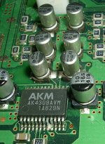
I think I can see an X-wing fighter begining it's attack run
Hehehe.
The solder joint between the two pins are I2S signals...
It works even if both are connected together. But maybe that's why I have to restart the PSX a couple of times to get sound.

Anyways, I have to get a new transport to make it work.
I don't want to modify it too much before other people do because I don't want to break it as I bought for 35$ /w shipping and I have to add an other 20$USD+ 20$ shipping for the transport.

Some people here get a working 100x + 2 controllers + memory card + remote for 25$!
I just have a 1001 /w one factory controller that will cost an other 50$ to make it work.
Re: Wow
It was not that much work. I used a small solder tip and the whole job took about 15 minutes. It is fully reversible also.
I did this on a spare board (the one that I fried). I do not intend to run it like this, as I dont have input caps on my amp.
Mick
jives11 said:
WOW Mick. So apart from Photography, you build nanobots by hand as well ? As my dad used to say " it takes a steady hand to split the atom".
So .... is it worth it? Was there much improvement ? My experience with an old CD104 philips player was that these caps did make a big difference to the sound.
It was not that much work. I used a small solder tip and the whole job took about 15 minutes. It is fully reversible also.
I did this on a spare board (the one that I fried). I do not intend to run it like this, as I dont have input caps on my amp.
Mick
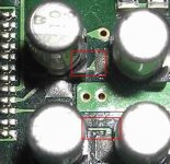
I found a German site, where it is claimed that the second pair of caps in the line are C423 and 424.
Look at this image
I verified the connection between pins 15 and 16 and the solder points at the first set of caps. Hmmmmm.....
Look at this image
I verified the connection between pins 15 and 16 and the solder points at the first set of caps. Hmmmmm.....
The DAC output is connected to both. I checked with my dmm. You can see it too.
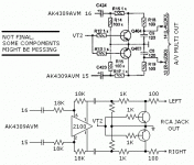
I'm currently checking while writing. What I can see is that there is a non-amplified circuit to the A/V jack and a circuit using an opamp to the RCA jacks. These all start by a cap and are connected in parallel from the DAC outputs.
I'm checking while writing and the first pair is going directly to the opamp. Also, the third pair of caps is connected thru some resistors to the RCA jacks.
The second pair is
cap output going to
100 ohm to ground in parallel to 1k ohm going to
100 ohm to A/V jack in parallel with transistor
The circuit of the second pair is the one from the scheme here:
http://www.diyaudio.com/forums/showthread.php?postid=774749#post774749
The circuit is not pretty interesting for us with the 100x ones as we are using the opamp circuit. At the same time, there are muting transistors also there.
If anyone wants, I can compare the A/V out with the RCA output as I have the A/V cable.
So: mods to try, disconnect the second pair of caps as it's unused, and short the first and third pairs of caps.
I can try to come with a scheme if people want.
Attachments
i just finished bypassing the caps.
there is big improvement do your best guys.
it sounds more detailed and more musical
a lot more.
and check out one thing.
my ps1 is the scph 5502.
i may be just lucky but i bypassed them under the pcb.
only the akm is surface mounted on my not the caps.
it was hard to find the points under the pcb but i did.
look carefully and triple check with the multimeter.
maybe it`s because of the model but give it a try.
OK so here's the output stage scheme of the 1001.
VT2 is what controls the muting transistors.
The only difference with the RCA jack compared to the A/V MULTI OUT is that there is an opamp. The schematic after the opamp's output is an exact copy of the a/v out scheme. I'm just not sure about the small caps directly @ the output connecting to ground.
Anyone here with a model without RCA jacks, is there only one pair of caps after the DAC? There is no opamp also. Am I right?
Attachments
Thanks!Good work, Dragonmaster!
Maybe your fried board just has a dead transistor or opamp. Have you tried the AV out?
With a stock board, I think that the A/V OUT is the best : The signal passes thru only one cap while the RCA jacks pass thru a chapo opamp and two caps. The traces are as tiny for both. The only advantage with the RCA jacks for now is the interconnects. The AV wire made by Sony seems pretty thin, but it's one of the best console A/V wire I know.(It didn't break, I broke two Nintendo cables in the same peroid of time)
A diode checker or ohmmeter will be your best friend. You will also need to be able to see what's on the PCB easily.First I have to retrace all the research you did on the output stage...
If you don't have the AV cable, you can use the test points as there are a lot of them.
DragonMaster said:.
Anyone here with a model without RCA jacks, is there only one pair of caps after the DAC? There is no opamp also. Am I right?
mick f `s sheme is correct for mine (5502) but it`s not the same for all models the 75xx 95xx and ps one don`t have opamps at all.
i guess opamps are good because the german guys say the older the better sounding.
the thing is that mine sounds fantastic after i shorted the caps.
i use good quality rca and i soldered them to the AV out pins.
another thing that gave me a good improvement was a power cable soldered directly to the psu at the power socket pins.
Mine or the one Mick posted which comes from here:mick f `s sheme is correct for mine (5502)
http://www.methe-family.de/cd.htm
Well that's what everybody tell but an ordinary JRC opamp is not the greatest I think.i guess opamps are good because the german guys say the older the better sounding.
A thing to try would be a classic PSU. What I think about is to put the regulators on a custom PCB that fits where the current one is and use somethign like a 9-12VDC wall-wart. This way, we keep the AC away and we only need a two-wire cable.
Also, the layout could be done so that we keep the current PSU switches. It will prevent us from having to select different ones.
DragonMaster said:The DAC output is connected to both. I checked with my dmm. You can see it too.
I'm currently checking while writing. What I can see is that there is a non-amplified circuit to the A/V jack and a circuit using an opamp to the RCA jacks. These all start by a cap and are connected in parallel from the DAC outputs.
I'm checking while writing and the first pair is going directly to the opamp. Also, the third pair of caps is connected thru some resistors to the RCA jacks.
The second pair is
cap output going to
100 ohm to ground in parallel to 1k ohm going to
100 ohm to A/V jack in parallel with transistor
The circuit of the second pair is the one from the scheme here:
http://www.diyaudio.com/forums/showthread.php?postid=774749#post774749
The circuit is not pretty interesting for us with the 100x ones as we are using the opamp circuit. At the same time, there are muting transistors also there.
If anyone wants, I can compare the A/V out with the RCA output as I have the A/V cable.
So: mods to try, disconnect the second pair of caps as it's unused, and short the first and third pairs of caps.
I can try to come with a scheme if people want.
So Dragonmaster, for users of the 1002, are you saying that to short 423 or 424 we must connect a wire from the +ve of the 1st capacitor to the -ve of the 3rd capacitor dans la avenue de la farad.
Why do they have 3 caps representing one on the circuit diagram ? Is it just a size thing ?
Why do they have 3 caps representing one on the circuit diagram ? Is it just a size thing ?
Because there are 3 different caps on the scheme. The circuit provided by MickF is for a newer version of the PSX that doesn't have the RCA jacks.
There are two independant circuit. If you want to remove all caps from the RCA jacks circuit, short the first and third pair. The first pair is before the opamp and the third is after the opamp. If you want to make the circuit like the A/V MULTI OUT, connect the input of the first cap to the output of the third.
The second pair is just for the unamplified A/V MULTI OUT.
I compared A/V MULTI OUT and the RCA jacks and A/V OUT seems to sound a bit better. It's unamplified, but the gain is the same as the amplified RCA outputs.
DragonMaster said:
Mine or the one Mick posted which comes from here:
http://www.methe-family.de/cd.htm
Well that's what everybody tell but an ordinary JRC opamp is not the greatest I think.
A thing to try would be a classic PSU. What I think about is to put the regulators on a custom PCB that fits where the current one is and use somethign like a 9-12VDC wall-wart. This way, we keep the AC away and we only need a two-wire cable.
Also, the layout could be done so that we keep the current PSU switches. It will prevent us from having to select different ones.
i mean the jrc maybe better than nothing.
about the psu i think that a wall wart is not enough 17w is 1.5A
i was thinking 3A minimum to have the best we can get.
anybody knows how we could have spdif output for use with an external DAC?
- Home
- Source & Line
- Digital Source
- Playstation as CD-player