Nope, nothing else.
Here's the text description:
1: 7.6v (Thru power switch)
2: Ground
3: 3.6v (Thru power switch)
4: Ground
5: 3.6v (Always on)
6: Ground
7: 3.6v (Reset sw / thru pwr switch, resets when switch disconnected)
The only thing I'm not sure about is that 2 pins of a 4-pin IC are connected between the reset switch and reset pin(7). Maybe it changes something when the switch is pressed or not.
Anyways, the voltage measured at the pin was 0 when reset is pushed and 3.6 if not.
I am not able to read the markings on the IC.
I guess a 12vAC transformer with two LM317 should work. I don't know if 1.5A is enough as the PSX with the current PSU uses 17w.
Maybe LM150 or LM138 would be safer in this case.
Mine measured 7.7v and 3.7v but a lot of sites with PlayStation info state that the voltages from the PSU are 3.6v and 7.6v.
Mick, do you know the use of the trimmer on the current PSU?
Mick_F said:
I would also be interested in a display but I am afraid that this is a bigger job....
A description of how to include a RC unit in the PS1 case is given here. Look at the latest update on the bottom of the page.
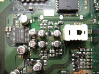
Attached is a schematic of the output stage.
Mick
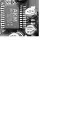
Thanks Mick_F for the output stage schematic. I'm new to surface mount and trying to figure out which is which. In my travesty of a crop of your original beautiful photo, I believe C423 & C424 are the 2 silver Cans to the right of the AKM DAC chip, they appear to have traces to pins 15 & 16. Is that correct ?
Attachments
the PS2 fan is too noisy for my tastes.
Crank up the sound!
Yes, I found a site on the Internet with the pinout for the 5-pin version.hi i have a scph 5502 and the psu conector have only 5 cables.
Here's the pinout:
1. 7.6v
2. GND
3. 3.6v
4. GND
5. Reset (3.6v when not pushed/ no more current when off)
They removed the pins 4/5 of the 7-pin version and pins 6/7 are replacing them.
Hmmm, like tiny ants ....
Well I stripped the PSone down, to clean it, check for hack-chips and genreally feel my way around. Mick_F's photos are fantastic BUT larger than life - those components are so small !. Removing the DC caps would definitely be a one-way street, I doub't I could get the caps back on having removed them.
Maybe I'll defer to the huge body of German knowledge on this subject, where they don't appear to modify the actual board
I agree with the connector pinout shown. There is just one thing I should tell you, although I am not sure what went wrong...
I once tried to make a connector with five leads (since I had a 5 pole cable and DIN connectors). I combined the three ground connections to one (2, 4, and 6) and used separate leads for 1,3,5, and 7. In principle this should work but when I connected the PS1 like this and switched it on I fried it. The mechanical parts worked but there was no sound. Later I tested everything with another PSU etc, but it remained silent, so I am sure I have irreversibly fried it.
It may be that something else went wrong, but, besides the common ground connection, it was a standard operation, which I have done before without any problems.....
I dont know what the trimmer is for.
Mick
Have you triple checked that the wiring was done right?
I really don't know what could have happened as the 3 grounds are connected together on the PSU PCB.
Maybe you reversed the pins of one of the connectors?
Did the other PSU you used had the factory short cable?
What do you mean by fried? It was smelling something or it's just that there was no sound?
Maybe the cable resistance is lowering the voltage?
If there was just no sound, try the stock cable with a PSU at it's normal location. You should try a couple of times to play a disc and to power it on and off it between each trials. My 1001 often starts the disc but no sound is going out. I have to play/pause a couple of times to get some sound.
jives11 said:
Thanks Mick_F for the output stage schematic. I'm new to surface mount and trying to figure out which is which. In my travesty of a crop of your original beautiful photo, I believe C423 & C424 are the 2 silver Cans to the right of the AKM DAC chip, they appear to have traces to pins 15 & 16. Is that correct ?
Unfortunately I only have the datasheet of the AK4309B, which has only 20 pins. But counting the pins, it seems that indeed 15 and 16 are connected to the two caps seen on your cropped image.
Does anyone of you have the 4309AVM datasheet?
Mick
Attachments
DragonMaster said:Have you triple checked that the wiring was done right?
I normally do so, and I am quite sure that I did then too.
I really don't know what could have happened as the 3 grounds are connected together on the PSU PCB.
I agree! It is a mystery to me too. But I am not going to try it once again....
Did the other PSU you used had the factory short cable?
Yes.
What do you mean by fried? It was smelling something or it's just that there was no sound?
Immediately after powering on I heard a grumbling noisy sound. I immediately switched off and checked the wiring. I could find no errors so I switched on again. This time I heard nothing, and this remained so even after I powered it up with another PSU and the short cable.
There was no smell.
Maybe the cable resistance is lowering the voltage?
I used a cable of about 1 m length. The leads were stranded 0.75mm. The corresponding voltage drop should be negligible.
If there was just no sound, try the stock cable with a PSU at it's normal location. You should try a couple of times to play a disc and to power it on and off it between each trials. My 1001 often starts the disc but no sound is going out. I have to play/pause a couple of times to get some sound.
Thats what I did, but it remained dead.
Mick
Well, I can't tell anything except maybe that two wires are soldered together but I doubt about that too. Have you chechek the resistance between each pins? Maybe two little bits of shield are missing somewhere?
I don't know what could have happened but maybe something happened in the way that the wires were twisted in the cable or something.
I don't know what could have happened but maybe something happened in the way that the wires were twisted in the cable or something.
back said:jives 11 why don`t you just bypass them with a piece of cable
to test the sound?
Thanks Back,
yes - of course you are right, I could short out the caps.
The problem is the 2 caps are surface mounts and next to each other. The board is double sided with no ways to jumper underneath.
To short out the caps I would need :
1) A better fine point soldering iron
2) Beta blocker medication to stop my shaking hands.
I could desolder the out tags and bend the caps off the board, but I need a much finer iron and more skill. My current iron wouldn't fit in the gap between the caps.
I'm extermely grateful to Mick_F for providing all of the data, but I think, on balance that I'd better stick with an unmodded PSone that works.
However the PSU would be easy to work on .....
I just made a request to AKM for it, we'll see in a couple of days!Does anyone of you have the 4309AVM datasheet?
The 4309B is supposed to be pin-compatible so I guess that we just have to find where are the 4 unused pins.
jives11 said:
Thanks Back,
yes - of course you are right, I could short out the caps.
The problem is the 2 caps are surface mounts and next to each other. The board is double sided with no ways to jumper underneath.
To short out the caps I would need :
1) A better fine point soldering iron
2) Beta blocker medication to stop my shaking hands.
I could desolder the out tags and bend the caps off the board, but I need a much finer iron and more skill. My current iron wouldn't fit in the gap between the caps.
I'm extermely grateful to Mick_F for providing all of the data, but I think, on balance that I'd better stick with an unmodded PSone that works.
However the PSU would be easy to work on .....
outs i didn`t like that.
my hands aren`t shaking but my solering iron
will be to big too.
i will check it out tomorow.
- Home
- Source & Line
- Digital Source
- Playstation as CD-player