Antoine, I'm talking about splitting the PCB, so the leads go between them. You still use the 7-pin connector.
As said, the idea is to keep the hot voltage regulator and transformer (?) away from the CDM.
I'm not saying this is ideal. But it sure beats making two PCBs. I haven't made any PCB in more than two decades and don't really feel like starting again. I assume it's a lot easier today, but still.
Once I have checked into this a bit more, I'll post back here.
phn said:Maybe I missed something in the thread, which I don't feel like re-reading. You guys say the PSX is (relatively) sensitive when it comes to cable and, I guess, pre/amp matching. (I don't have any mismatch problem. I ask here in general.) What exactly does the PSX want? 47kOhms was standard for tube gear back in the day. It still seems to be something of an accepted standard, at least outside of high-end audio.
See
http://www.diyaudio.com/forums/showthread.php?postid=870311#post870311
Thomas
phn said:...
The PSX SMPS is complex. But to me it gets a bit easier when you split it in two at the two big diodes. I was considering rebuilding it as two PCBs, keeping the parts that get hot away from the PSX. That way I would need a cable with only two leads. It will still be complicated as far as I'm concerned. But if you must re/make a PSU, I think this is the best alternative.
AFAIK this concerns to the (nichicon-made) model 1-468-159-11, only.
Nice idea IMHO.
Thomas
phn said:...
The PSX SMPS is complex. But to me it gets a bit easier when you split it in two at the two big diodes. I was considering rebuilding it as two PCBs, keeping the parts that get hot away from the PSX. That way I would need a cable with only two leads. It will still be complicated as far as I'm concerned. But if you must re/make a PSU, I think this is the best alternative.
thokra2003 said:
AFAIK this concerns to the (nichicon-made) model 1-468-159-11, only.
Nice idea IMHO.
Thomas
What to do with PC001 ?
Thomas
phn said:Well, the first thing really is to get one of those new/spare PSX SMPSs for the PSX.
...
Definitely not, bcs. the spare SMPS is usually of minor quality.
phn said:... I would think that after a decade, those electrolytics are not that healthy. The PSX was used by kids that played it hours on end.
...
Better replace the electrolytics with recent 105° grade caps. For example Rubycon ZL will work fine.
Best
Thomas
thokra2003 said:
AFAIK this concerns to the (nichicon-made) model 1-468-159-11, only.
Nice idea IMHO.
Thomas
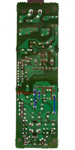
That might be true. I made a mistake though. You will need 5, not 3 leads. 3 works in the schematics but not with the PCB layout. I forgot the PC1001 IC. I guess that's the reason they say "measure 2 times before you cut" over at the speaker section.
I also noticed my drawing has one error, but is basically correct.
A stupid questin about the reset switch. I guess I don't trust myself. As a non-professional, I'm VERY cautious, ridiculously so, around electronics. I will never get confident around tube gear and the fact that you can fry eggs on them. The repeated 230 V jolts (including from the stupid PSX PSU) and subsequent temporary numbness in my hand haven't helped much. (I'm aware of the contradiction of repeated jolts and cautiousness. There's no cure for stupidity.)
I have no use for the reset switch. My multimeter tells me that you can just remove it and the PSU will work all the same. Am I right?
I have no use for the reset switch. My multimeter tells me that you can just remove it and the PSU will work all the same. Am I right?
I await the missing gospel from :
http://www.dogbreath.de/PS1/index.html
On recasing the power supply
Mick I hope your photographic exhibition went well and you can return to your main vocation
http://www.dogbreath.de/PS1/index.html
On recasing the power supply
Mick I hope your photographic exhibition went well and you can return to your main vocation
Sorry for spamming the tread. But the earlier EAMX5 (?) PCB will work. It will be even easier since you can cut it in a straight line. Don't take my word for it just yet, but it sure looks that way. Again you will need five leads. In any event, this is the one I will try to work with.
DragonMaster, if your reply is for me, I'm lost. But that's the least of my problems right now. I have a PCB to look into.
Added an image of the old PCB. Remember, double check before you cut it.
DragonMaster, if your reply is for me, I'm lost. But that's the least of my problems right now. I have a PCB to look into.
Added an image of the old PCB. Remember, double check before you cut it.
Attachments
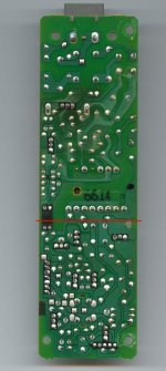
My EAMX5 board just went up in smoke. The big cap had come loose, so I tried to repair the board. I then checked the outputs and got 4 V from them all!? Then I'm not sure, but it went wham and the room went black, sparks flying and the probes melted.
The board didn't look healthy to begin with. Cracked and discolored. Now it's retired.
The board didn't look healthy to begin with. Cracked and discolored. Now it's retired.
DragonMaster said:Strange things happen with these SMPSes...
You can say that again, Antoine!
I spent some time this weekend working over two of my three SMPS's... initially replaced most of the electrolytic caps except the initial large cap) with Rubycon ZA/ZL caps, then did a 2nd phase where I replaced the diode bridge with Stealth Ultra-Soft-Recovery diodes and the initial large cap with a Jensen 4-pole cap.
I did the phase 1 cap replacement on one of my SR670 SMPS's first... listened for a couple hours, inital (pre-breakin) signs were nice... better delineation of details, a bit more neutral frequency balance (a bit less dark). Encouraged, I did the phase 1 on my EAMX5 SMPS... up to then my fav PS. A bit of listening and I was disappointed... the increased delineation of details was there, but it was accompanied by a hash or harshness in the upper-mids and above... it sounded sorta 'Whiny' or 'Shouty'. OK... maybe it needed more upgrading, so I did the phase 2 on it... even better delineation, but the 'Whininess' persisted. Oh well, I did all the mods so I could reverse them if I needed to, so I went on and did the phase 2 diodes and Jensen 4-pole to the SR670... and it got better without the 'Whininess'.
Ok, maybe they need more breakin... they both had less than 24 hours so far. So I ran them constantly overnight and listened again... SR670 kept getting better as it ran-in, but the EAMX5 stayed a bit off.
Without going into lotsa details, I tried a bunch of things and found I needed to reposition the initial input filtering cap on the EAMX5 (originally a .1 uf, now a .68uf)... I'd moved it and the choke filter around a bit to make room for the large Jensen cap. With it directly across the power cord socket, it's showing promise.
I consider this all preliminary... I'll give them both a week or two to burn-in and then compare them to my stock SR670 (and another EAMX5 if I can find one).
But the EAMX5 had me going for awhile!
Greg in Minneapolis
P.S. I'll take and post pix later... but for you 'keep the top on' types, there's no way these mods could be done and have the SMPS still fit in the case.
P.P.S phn, sorry to hear about your EAMX5 smoking.
Yeah, I hate losing the PSU. Not because of money, but because I don't have that many to waste.
I will buy two of those new ones to play around with. Cut them in two, to be more exact.
By the by, does anyone know why you cannot use the controller and remote at the same time? I want controls on the console as well as a remote. The remote is junk, but I do like the Pause button when the phone rings.
Why?
Phn...
I've been meaning to ask what you plan to accomplish by cutting them in half?
Given some of the radical things I've done to my PS's, I'm not the one to be the skeptic.... OTOH, I wonder if the inductance in the leads of any length after the transformer might cause problems with the output rectification and be a source of radiated noise.
Just curious... and if it turns out to work well, I'll be sawing on mine the next weekend!
Greg in Minneapolis
P.S. I was disparing of the sound of my component mods in my SMPS's the last couple days, but at least one of them is beginning to sound pretty respectable today... I couldn't find a lot of info on the breakin time of the components I used, but what little I saw suggested pretty long... 100-400 hours... and I'm barely up to 100 hours on-time tonight. I need to listen to the other one too.
phn said:<SNIP>
I will buy two of those new ones to play around with. Cut them in two, to be more exact.
<SNIP>
Phn...
I've been meaning to ask what you plan to accomplish by cutting them in half?
Given some of the radical things I've done to my PS's, I'm not the one to be the skeptic.... OTOH, I wonder if the inductance in the leads of any length after the transformer might cause problems with the output rectification and be a source of radiated noise.
Just curious... and if it turns out to work well, I'll be sawing on mine the next weekend!
Greg in Minneapolis
P.S. I was disparing of the sound of my component mods in my SMPS's the last couple days, but at least one of them is beginning to sound pretty respectable today... I couldn't find a lot of info on the breakin time of the components I used, but what little I saw suggested pretty long... 100-400 hours... and I'm barely up to 100 hours on-time tonight. I need to listen to the other one too.
Dommi said:@Mick
If you push the board, isn't it so that the time the board oszillate depens also at the pressure you push it ?
I dont think that this is really a methode to check the resonance frequency. As i know the resonance frequency is the frequency at the time that the support began to swing with the same frequency like the disruption. Isn't it so ? With your methode you can only check which frequency can be absorbed in which time, but this make no diclaration about the quality of the support i think.
BR Dommi
Dommi, it is approximate but not so bad to determine the resonance frequency this way.
To be more precise, what you try to determine is the "Eigenfrequency" of the system. The eigenfrequency is only given by the mass and the spring constant (i.e. the properties of the tube) and in a good approximation independent of the amplitude of excitation. If excited, i.e. pushed to a certain amplitude, the system will return to its resting position by oscillation with its Eigenfrequency.
The term "resonance" comes into play when the system is excited periodically with a frequency equal or close to the Eigenfrequency. Then, the amplitude becomes large, which is, in our application, not preferrable.
Mick
On the SMPS:
I currently use the stock SMPS in a separate case and it works fine, some sonic improvement with respect to the original position is audible. I use a seven-lead connector at the moment.
As Antoine pointed out, I once tried to use a five-lead cable by combining the three grounds to one. When I switched the PS1 on in this modification, I fried it. I dont know what precisely the problem was, but there was no sound, even when I went back to the original arrangement. However, I am meanwhile quite sure that there must have been some other problem that has caused the breakdown. I cannot exclude that during the process I shorted something or so...
I think, theoretically one can reduce the number of leads to three. Just one for 3.6 V, one for 7.6 and one for ground.
Jonathan, my exhibition opens April 28. I am ready with the printing. Still some framing, spotting, etc. left to do.....
Mick
PS Why should the SPMPS board be cut???
- Home
- Source & Line
- Digital Source
- Playstation as CD-player