Dragonmaster, I have finally found the time to check your schematic of the RCA output stage. I could confirm everything.
One thing that surprised me is that the value of the resistors from the output of the third pair of caps to ground (and to the emitter of the muting transistors) seems to be only 1k in the RCA circuit. In the AVout circuit this resistor is a 100k. Can you confirm this?
Mick
One thing that surprised me is that the value of the resistors from the output of the third pair of caps to ground (and to the emitter of the muting transistors) seems to be only 1k in the RCA circuit. In the AVout circuit this resistor is a 100k. Can you confirm this?
Mick
Well what I can see is that there is a 1k(from capacitor pad) going to the muting transistor and to the 100 ohm going to the output with both A/V and RCA circuits.
But the 100ks I see are going to ground connecting at the same capacitor pad as the 1k. That's for both AV and RCA.
You should make sure to look at the good via when going from one side to an other. It's easy to pick the wrong one.
But the 100ks I see are going to ground connecting at the same capacitor pad as the 1k. That's for both AV and RCA.
You should make sure to look at the good via when going from one side to an other. It's easy to pick the wrong one.
Re: Unidentified Soldered Object (USO)
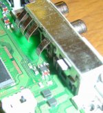
below shows the offending object. Anyone know what function it serves , it's the small block with red ends, approximately central but near the right output RCA
jives11 said:
On my SCPH 1002 if I trace the Left & Right signals from the DAC, past the opamps then close to the RCA sockets. The traces seem to converge around a dark gray block with 6 solder pads and red ends. It appears to be in series with the signal and has resistance lower than I can measure , so I guess it's not a transformer. It's much bigger than the transistors.
Anyone know what this is ?
below shows the offending object. Anyone know what function it serves , it's the small block with red ends, approximately central but near the right output RCA
Attachments
I second that.Please, really, in a few words, could you sum up your modifications?
Pleeeease

A summation would be very useful.
Mick_F said:Dragonmaster, I have finally found the time to check your schematic of the RCA output stage. I could confirm everything.
One thing that surprised me is that the value of the resistors from the output of the third pair of caps to ground (and to the emitter of the muting transistors) seems to be only 1k in the RCA circuit. In the AVout circuit this resistor is a 100k. Can you confirm this?
Mick
Might need a large value of DC blocker then ?
Please, really, in a few words, could you sum up your modifications?
http://www.diyaudio.com/forums/showthread.php?postid=784185#post784185
Tell if you want details on them.
Might need a large value of DC blocker then ?
It's : http://www.diyaudio.com/forums/showthread.php?postid=784214#post784214
<so as I understand it, in your design there is a direct signal path <with no caps, resistors, opamps or muting transistors.
Hy,
i've done following:For the power unit i changed the diodes and used faster one. I changed all caps to MKP. I covered all caps, diodes etc. with lute.(??)
Than i shielded the power board with copper
On main board :
I desoldered the 6 Caps. On the first cap near the AVM ( C429 and C430 ) i soldered a shielded wire at the neg. pad. This i soldered with a new oil/paper cap which is outside the original PS Case. Than i connected a shielded wire from the oil/paper cap to the positiv pin of the RCA which is outside the original PS case, too. I connected the neg. pin with the shielding, and with a ground point of the board. Than i soldered a 1MOhm resistor parallel to the RAC jacks.
The sound intensity is about 5db lower as with op.
At the two caps right and left the AVM i soldered a small fast cap parallel.
Now i will cover all caps and ic's with lute (??) to avoid microfone effects.
I mounted the Laserunit on fixed thread-rods.
On my HP there are some pictures of the old modification .
If you want i will make some pictures of the new mod and set them here, if i can find out how to do ;-))
The power for the blue led came from the 5V DC out at the rear of the PS.
I can't recommend to use the PS without DC-Filter CAP whan you don't know if your pre have one inside the IN STAGE. Most pre haven' t one or only a small one.
Take care if you have a tube amp !!!!!
<I guess the 100Ohn resistors you speak of are beneath the <board. Do you know which ones there are in Dragonmasters <picture of removing the mute transistors ?
I don't know which resistors you have to remove, i don't need to remove them because i use external jacks. Sorry.
BR Dommi
Dommi said:Hy @all,
this morning i phoned to a friend because of the wrong caps i changed, and i thought to hear a difference. Now we are gonig to check it out with a blind test to debar suggestion. We will take one original PS1 and one with changed C424 and C423. I'm verry nosy if there is a difference or not. I will inform you.
BR Dommi
Hy @all,
we checked half a day and it`s really so, that i can't hear any differences with blind tests.

I will now invite some other PS owner which also heard a difference only with changed C423 and C424 and use the RCA jacks.
For the sound with the new mod i will report as soon as possible. I will check it out with a blind test again !!!!!!!!
BR Dommi
kmj said:Dommi
Why the paper/oil caps? are they that much better than audiograde Polypropylens?
I don't checked it in my current configuration, but i made good experience with the paper/oil caps at other modifications.
Regards Dommi
Rodeodave said:Please, really, in a few words, could you sum up your modifications?
i guess it`s for me so here we go.
dc block caps c 423 c 424 bypassed.
unsoldered muting transistors Q 403 Q 404.
after that nothing is between the DAC and the output except 2 resistors per channel 1k and 100 ohm in series with the signal and two more 100k parallel from output to ground.
new linear regulated power supply 7A.
screwed with rubber feet on a piece af heavy wood (i will build a wooden box later)
everything was done in steps and every step improved
the sound.
Re: Re: Unidentified Soldered Object (USO)
But Guys ?
This device appears to be in the RCA signal path. Am I being (more) stupid ? It's just that while we are moving toward minimalist signal paths we should understand what this is
http://www.diyaudio.com/forums/showthread.php?postid=784238#post784238
jives11 said:
below shows the offending object. Anyone know what function it serves , it's the small block with red ends, approximately central but near the right output RCA
But Guys ?
This device appears to be in the RCA signal path. Am I being (more) stupid ? It's just that while we are moving toward minimalist signal paths we should understand what this is
http://www.diyaudio.com/forums/showthread.php?postid=784238#post784238
DragonMaster said:Well what I can see is that there is a 1k(from capacitor pad) going to the muting transistor and to the 100 ohm going to the output with both A/V and RCA circuits.
But the 100ks I see are going to ground connecting at the same capacitor pad as the 1k. That's for both AV and RCA.
You should make sure to look at the good via when going from one side to an other. It's easy to pick the wrong one.
I could confirm the 1k and 100R in series before the output (between which the connection to the muting trans is made). I will check the other R going to ground once again.
It would be strange if they had such a low value, in particular to the high cutoff frequency that would result.
I'll be back with this later on.
Mick
Re: Re: Re: Unidentified Soldered Object (USO)
Jives, I have also noticed this little thing and have no idea what it is. My current way to go is to use the AV path. (Remove the second set of caps, then a 4.7 uF and 1k in series to an external RCA and a 22k to ground after the cap.
The advantage of this mod is that is avoids all internal circuitry after the DAC (including the unknown thing), and the normal RCA output can still be used. No irreversible operations have to be performed on the normal RCA circuit.
Mick
jives11 said:
But Guys ?
This device appears to be in the RCA signal path. Am I being (more) stupid ? It's just that while we are moving toward minimalist signal paths we should understand what this is
http://www.diyaudio.com/forums/showthread.php?postid=784238#post784238
Jives, I have also noticed this little thing and have no idea what it is. My current way to go is to use the AV path. (Remove the second set of caps, then a 4.7 uF and 1k in series to an external RCA and a 22k to ground after the cap.
The advantage of this mod is that is avoids all internal circuitry after the DAC (including the unknown thing), and the normal RCA output can still be used. No irreversible operations have to be performed on the normal RCA circuit.
Mick
- Home
- Source & Line
- Digital Source
- Playstation as CD-player