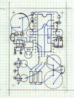
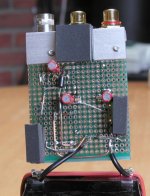
I was working recently on a compact layout for TDA1543 DAC and I came with this configuration. To simplify I2S connection TDA chip supposed to be on a bottom layer. I was almost completely satisfied with this solution, when suddenly an idea struck my head")
I got reminded about all those fancy ground plane talk, minimizing inductance and capacitance, and of course 3D layout techniques used in Connosseur preamps.
So I decided to break the envelope of 2 dimentional assembly plane and get more adventurous.
I got reminded about all those fancy ground plane talk, minimizing inductance and capacitance, and of course 3D layout techniques used in Connosseur preamps.
So I decided to break the envelope of 2 dimentional assembly plane and get more adventurous.
Attachments
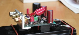
I started with attaching copper foil to the top of CS8412 chip (thinner grade from Alpha core inductors using double sided adhesive tape). I attached later TDA1543 chip on top with BCK an FSYNK lines directly aligned on both chips. This leave the DATA line only slightly longer , but still as short as it gets.
All the regualtors (AN800x) ae attached directly to chip pins, their ground pins directly to copper plane. All bypass electrolytics are attache directly to chip pins (BG N 4.7 mostly)
The other chip visible in a pic is the input buffer (from Kusunoki DAC3). I used Vishay S102 to terminate the input.
Attachments
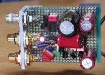
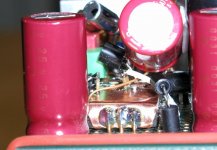
All connections are as short as possible. I decided to use 12V battery to power the whole thing with 4 separate regulators. I will later try 2 batteries (separate for DAC and receiver). The sound is really good and comparing to AC power it seems to be more realxed and smooth, but the difference is not that big. Initially I had 2200/16 BG cap to prefilter DAC regualtor, but it seems that the sound is better with out that cap.
Attachments
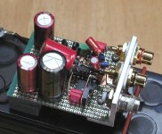
In some other thread, there was a discussion about ceramic bypass caps. Well, that DAC was initially built without them, as I wanted to check out their influence. Comparing what I remembered from the sound of my other DACs (having those caps) the sound seemed to be dry and not liquid enough, lacking a bit of sparkle. After adding ceramic bypasses, it improved. I don't know what other guys are using, but the caps I favour are 15n X7R 0612 and 330n X7R 0612 from DK. They are pretty expensive and have soldering tabs on longer side, being even more suitable for bypass purposes. I solder tham directly to the chip pins, stack on each other, the smaller one being closer to the chip.
Here's the link to excellent article by Pete Goudreu discussing triplets bypassing http://groups.google.com/groups?selm=4te25c$hcn@agate.berkeley.edu&output=gplain
Here's the link to excellent article by Pete Goudreu discussing triplets bypassing http://groups.google.com/groups?selm=4te25c$hcn@agate.berkeley.edu&output=gplain
Attachments
Some people complain about CS8412 and spdif interface, yet this DAC, when used with CD Pro2 connected with Kimber Iluminations D-60, BNC termianted cable, sounds much better than my modified battery driven Marantz CD-94 (I2S direct) with non oversampling mod, Tent clock, synchronous reclocking and active, discreet output stage. I will be modifying Marantz again (soon)
The Marantz still posses traces of digital haze, while this setup is free from any digital artifacts.
The Marantz still posses traces of digital haze, while this setup is free from any digital artifacts.
Very,very good Peter!
I like it a lot!
Do you have any drawn schematics? Maybe I will try TDA1543 again.
Is the output stage and I-V passive (I think it is)?
Have you compared CD 94 and CD-PRO as a transport only.
CD 94 is equipped with CDM 1.I guess it should be better than CD-PRO.
Bartek
I like it a lot!
Do you have any drawn schematics? Maybe I will try TDA1543 again.
Is the output stage and I-V passive (I think it is)?
Have you compared CD 94 and CD-PRO as a transport only.
CD 94 is equipped with CDM 1.I guess it should be better than CD-PRO.
Bartek
CD Pro is better than Marantz as a transport, but I imagine there other things (beside transport) influencing performance (PS for instance, which is not modified in Marantz.
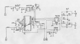
Here's the schematic. There is also a raw PS, I'm not showing here, but it is mostly based on Kusunoki DAC1 with extensive CLCRC filtering. If run from batteries it gets much simpler and some cap maybe omitted. I noticed that less capacitance makes things sound better. I didn't use 22R resistors on I2S as those connections were very short in my layout. On ea. chip supply pins are 15n and 330n ceramic SMD caps. All bypass caps are BG N type (they are simply the best in this application. I/V and ref resistors are Rikens (get the closest available values). If built as shown, this DAC presents tremendous value (performance wise).
PS: I noticed that in Kusunoki schematic power to pin 24 is taken from digital supply. Any particualr reason and importance of that?
Attachments
Hi Peter
I love your techno sculpture
As I wish to produce a small unit for my portable, I have been
thinking along these lines myself..
I have not started doing any making as yet, just planning.
And of course worrying about scopes!
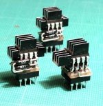
Here is a pic of a couple of Buffer[stack] attack modules I made.
[adapter to convert HA 5002s to BUF634 pin-outs.]
Cheers
Setmenu
I love your techno sculpture
As I wish to produce a small unit for my portable, I have been
thinking along these lines myself..
I have not started doing any making as yet, just planning.
And of course worrying about scopes!
Here is a pic of a couple of Buffer[stack] attack modules I made.
[adapter to convert HA 5002s to BUF634 pin-outs.]
Cheers
Setmenu
Attachments
Peter Daniel said:Why people seem to be preocupied with heatsinking those chips? If you use a copper foil ground plane and glue the cheap (upside down) to it, you will achieve both heatsinking and additionally, very good groundplane with short connections for any bypassing purposes.
Is there any problem in soldering things on the copper foil, when it's already placed on the chip?
Bricolo said:
Is there any problem in soldering things on the copper foil, when it's already placed on the chip?
The only problem is with adhesive tape. When regular double sided tape is used, it melts. I'm using here the thick, white stuff, that is used to attach security devices (in stores ).
zygibajt said:Thanks a lot Peter for schem.
Are you omiting all of those regulators with batteries?
What voltages of batteries are you using?
Bartek
You need the regualtors as the battery is 12V and PS to DAC is 8V and other chips are powerd by 5V. Those Panasonic TO-92 reg. are especially good and I prefer them to LM337 and even Elso's discreet regualtor
Hi Peter
Sorry they offend!
I only posted them for fun, I thought they looked quite statuesque
The approach you suggest would have been impossible to implement in the application they were intended for.
I had no intention of spoiling your thread
As the image has no relevance here.
But I guess my enthusiasm got the better of me
Please feel free to have it deleted.
Setmenu
Peter Daniel said:Why people seem to be preocupied with heatsinking those chips? If you use a copper foil ground plane and glue the cheap (upside down) to it, you will achieve both heatsinking and additionally, very good groundplane with short connections for any bypassing purposes.
Sorry they offend!
I only posted them for fun, I thought they looked quite statuesque
The approach you suggest would have been impossible to implement in the application they were intended for.
I had no intention of spoiling your thread
As the image has no relevance here.
But I guess my enthusiasm got the better of me
Please feel free to have it deleted.
Setmenu
setmenu said:
Please feel free to have it deleted.
It is me who should be sorry that you felt that way. They don't offend at all and as they say a picture is worth a thousnad words
I just don't understand why people are concerned with heatsinking those chips and going to such extends. They don't run that hot
I've noticed that silver mica caps are popular with German audiophiles. I never really tried them. Here's what Jonathan Carr says about them
http://www.diyaudio.com/forums/showthread.php?s=&postid=262664#post262664
http://www.diyaudio.com/forums/showthread.php?s=&postid=262664#post262664
- Status
- This old topic is closed. If you want to reopen this topic, contact a moderator using the "Report Post" button.
- Home
- Source & Line
- Digital Source
- The ultimate TDA1543 DAC layout??