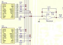
Reason why is, I have this dac that has paralleled PCM1704's with a dual opamp I/V that only uses one, the other is not used, and I've replaced with the dual AD826 which I can parallel the other half as above.
Cheers George
Cheers George
Attachments
Last edited:
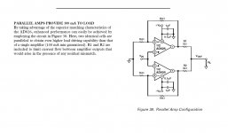
If you use the right scaling resistors ( ~5.4k//110pF from each - input to output),
and ground the +Vin terminals.
There will be lower common mode distortion for the inverting mode operation.
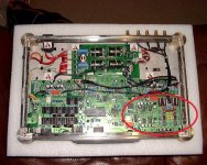
This sound promising, when you say the right scaling resistors, couldn't the 2.7k already in the second pic with the 221pf filter cap across it be used?
Any more suggestion to guide me through this?
Cheers George
Last edited:
This sound promising, when you say the right scaling resistors, couldn't the 2.7k
already in the second pic with the 221pf filter cap across it be used?
Possibly, if the current output can drive it to the right level. The data sheet says
only 1mA peak max output current though. To get the nominal 2V out, you'd need
to double the feedback resistors, since the current is halved into each op amp circuit.
Also I'd try breadboarding the circuit. There may be some parasitics to deal with,
for example with stopper resistors in series with the -inputs, etc.
Last edited:
Each 1704 dac is 1kohm output impedance and +-1.2mA output, and there are 2.
Right, you may be able to make the 2Vrms level with those values.
1.2mA x 2.7k = 3.24Vpeak or 2.29Vrms.
Last edited:
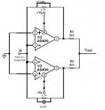
How does this look.
That's the idea, but you need to see how well it actually works in operation.
Do you have a 100MHz scope to see hf oscillations? These 50MHz wide bandwidth
op amps will almost certainly require a ground plane to work cleanly.
Last edited:

Yep, got a good scope, and there is a good ground for it, I'll get around to it in a few days and report back.
Use SMT parts if possible, with a compact layout, solid ground plane, and good hf bypassing.
I think the two half-opamps are going to be fighting each other due to slight differences
in input offset voltage. I reckon you'll need some 'sharing' resistors at the inputs,
rather like the two 5R at the outputs.
Pretty sure something like that will happen.
I think the two half-opamps are going to be fighting each other due to slight differences in input offset voltage. I reckon you'll need some 'sharing' resistors at the inputs, rather like the two 5R at the outputs.
Hi Araxalito, How will I tell if I need them, and 5ohm ok?
Do you think this could be better than just one AD826, will I gain the above?
EG: (lower input impedance, better distortion, better drive, headroom?}
And will gain remain the same?
Cheers george
The fighting will manifest as one (or both) of the opamps outputs hitting one or other of the supply rails. 5R would be a starting point for experiments yeah.
But why not use one of googlyone's discrete opamps (on his blog)? The advantage there is classA operation in the output stage so no noisy power supplies hence no fancy decoupling schemes required.
But why not use one of googlyone's discrete opamps (on his blog)? The advantage there is classA operation in the output stage so no noisy power supplies hence no fancy decoupling schemes required.
Why bother. You are making a solution to a problem that does not exist.
Just put an OPA627 single in its place and jumper pins to the right positions.
That way you will have a much better sounding op-amp replacing what you had before.
Some say the AD826 is better for I/V duties as it slew rate 350v/us where the OPA627 is only 55v/us
And settling time is 70ns for the AD826 where the OPA627 is 550ns
Cheers George
But why not use one of googlyone's discrete opamps (on his blog)? The advantage there is classA operation in the output stage so no noisy power supplies hence no fancy decoupling schemes required.
Got a link to his site, searched here couldn't find anything.
Cheers George
- Status
- This old topic is closed. If you want to reopen this topic, contact a moderator using the "Report Post" button.
- Home
- Source & Line
- Digital Source
- Calling all I/V gurus