So all this Calvin, with the NE5532's is to get rid of DAC noise after the I/V stage?
Any goodness to having this?
The PCM1704 from what I gather is quite re noise/glitches
My other Cary unit has a single PCM1704 with the AD844 (no fb) I/V and just has a simple cap across the TZ gain resistor for -3db 120khz and I see very little noise on the scope maybe a couple of uV thats all, and certainly don't hear any.
Cheers George
Last edited:
Hi,
TI writes about the measuring conditions of the PCM17104 on p6 of their DS ("DC Specification - Idle channel SNR").
As they obviously think, that customers order parts only after figures and price they bandlimited the output to press the last few dB of SNR out of the lemon.
Since the PCM1704 is a SignMagnitude DAC it doesn´t suffer from sharply rising HF-noise as oversampled noiseshaped systems do (one major reason why DSD is such a sucker imho)
Also the internal DACs are fed with upsampled data (8x CD or DVD, hence 352.8kHz or 768kHz), so that the rising HF-noise break frequency is far above the audio band.
I don´t know which digital filter character is used ahead of the PCM1704s, but all modern filters offer >100dB attenuation outside the passband.
The KlangKling looks like a slightly modified Datasheet implementation of the PCM1702 DS-application Fig.4 P.8.
But there´s no need at all to apply such steep analog post filtering.
It´ll probabely only make 1-3dB difference in SNR at a noise measurement bandwidth of >100kHz.
If You limit the measurement to the audio bandwidth it´ll probabely dosen´t change a jota in SNR figure.
A 1st order filter to limit the analog stages bandwidth and to keep RFI out is all what´s required here.
Certainly those unnecessary steep filtering influences on sonic performance even if there seems no direct measurable influence in the audio band.
I guess omitting with the OPAmp based IV, Filter and Buffer and implementing a discrete IV (or the AD844/OPA861), a simple 1st order lowpass and a decent Buffer will lift the KlingKlang to new levels of sonic performance")
jauu
Calvin
ps. You might want to have a look at TI´s Application Report SLEA048-May2005 "Out-of-Band Noise and Filtering for PCM DAC"
In that report noise measurements are taken for oversampling noiseshaping DACs and the influence of different filtering on SNR figures @100kHz.
TI writes about the measuring conditions of the PCM17104 on p6 of their DS ("DC Specification - Idle channel SNR").
As they obviously think, that customers order parts only after figures and price they bandlimited the output to press the last few dB of SNR out of the lemon.
Since the PCM1704 is a SignMagnitude DAC it doesn´t suffer from sharply rising HF-noise as oversampled noiseshaped systems do (one major reason why DSD is such a sucker imho)
Also the internal DACs are fed with upsampled data (8x CD or DVD, hence 352.8kHz or 768kHz), so that the rising HF-noise break frequency is far above the audio band.
I don´t know which digital filter character is used ahead of the PCM1704s, but all modern filters offer >100dB attenuation outside the passband.
The KlangKling looks like a slightly modified Datasheet implementation of the PCM1702 DS-application Fig.4 P.8.
But there´s no need at all to apply such steep analog post filtering.
It´ll probabely only make 1-3dB difference in SNR at a noise measurement bandwidth of >100kHz.
If You limit the measurement to the audio bandwidth it´ll probabely dosen´t change a jota in SNR figure.
A 1st order filter to limit the analog stages bandwidth and to keep RFI out is all what´s required here.
Certainly those unnecessary steep filtering influences on sonic performance even if there seems no direct measurable influence in the audio band.
I guess omitting with the OPAmp based IV, Filter and Buffer and implementing a discrete IV (or the AD844/OPA861), a simple 1st order lowpass and a decent Buffer will lift the KlingKlang to new levels of sonic performance
jauu
Calvin
ps. You might want to have a look at TI´s Application Report SLEA048-May2005 "Out-of-Band Noise and Filtering for PCM DAC"
In that report noise measurements are taken for oversampling noiseshaping DACs and the influence of different filtering on SNR figures @100kHz.
Last edited:
Are the ISL28210s unity gain stable?
Yep.
If you're still looking for tweaks I'd investigate how the opamps are decoupled. Most likely due to the presence of groundfill, the signal and power grounds aren't separate, meaning rail noise will get coupled into the signal. Its a fair amount of work to prise the two GNDs apart, though in my experience well worth the effort.
@Calvin - I did indeed miss the AG

Hi,
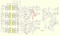
if You pull the OPAmps then the GIC impedances are connected to AG at both ends .... at Z5 (C154) and via R144/R126/C130 at the other end (Z1, C150).
The current input Pin2 of U28a is connected via a high-impedance path (R152/C174/R148/R126/C130) to AG, which would be negligable to the low impedance Input of a IV converter that'd be connected to Pin2 also (quasi in parallel).
Towards the output, Pin1 of U17a is connected via R112/C117/R118 to AG.
If left in place this network would preload a new buffer.
The 20k/4F should not present an issue for any buffer though.
So, for tests the passive parts may be left in place wo ill effects.
jauu
Calvin
Last edited:
Hi,
do You want to use the sockets as connectors for a new IV and Buffer?
Then you could principally proceed as described.
Bridge out R148 also as only R144 and C130 would be required.
R144´s value is too high and C130´s value too low, so that paralleling a resistor to R144 and a Cap to C130 is needed to provide for the right values (or replacing both parts with the correct ones).
Paralleling R144 with 1k5 results in a resistance of ~1k2 and a voltage of 2Vrms at the IV converter´s output.
After the formula F=1/(2pi RC), paralleling 1nF to C130 will give 1.1nF and F~122kHz
jauu
Calvin
Hi Calvin, at first to see I was just going to use the OPA2604's as they are for I/V and buffer. (later I will try something else)
What about this, R126 and R148 bridged out, C150 lifted at one end?
And add another 100pf across C130 (for 222pf), this with the 5.6k of R144 for a LP filter at -3db at 128khz?
Cheers George
What about this, R126 and R148 bridged out, C150 lifted at one end?
And add another 100pf across C130 (for 222pf), this with the 5.6k of R144 for a LP filter at -3db at 128khz?
Cheers George
Hi,
in general ... it depends
In simulation the following levels should occur:
Pin1(U28a): The peak voltage at 0dBfs calculates to Idacpp x 2k7 = +-6.48Vpp = 4.58Vrms = +13.22dBV (Idac is +-2.4mA here).
But let´s assume this as 0dB reference point and all numbers @1kHz.
Node R148/GIC/ff: -4.3dB
Pin3(U17a): -4.3dB
Node C82/R107/FF: +1.7dB
Pin4(T.OUT) into >10kOhm: +1.7dB
Pin4(CD OUT) into >10kOhm: +0.68dB
So T.OUT is at app. +14.9dBV ~ 5.57Vrms and CD-Out at app. +13.9dBV ~ 4.96Vrms
If Your new IV-converters Riv is chosen to put out the same voltage as measurable at Node C82/R17/FF and assuming the new Buffers gain would be 1, hence 0dB, then the exakt same voltages would appear at T.Out and CD_Out.
This would be the case if Riv is chosen as 3k28 (3k3 as next value).
As most poweramps are driven fully by ~1Vrms levels of ~ +13dBV-15dBV are much morer than required.
I´d rather opt for +6dBV (2Vrms, Riv=1k2).
jauu
Calvin
- Status
- This old topic is closed. If you want to reopen this topic, contact a moderator using the "Report Post" button.
- Home
- Source & Line
- Digital Source
- Anyone work this out?????